To be clear up front: I’ve never actually had the brakes fade on me. The problem has always been heat cooking the hardware. I’ve overheated the rears plenty of times, and eventually the ceramic piston tips in the calipers disintegrated from the heat — front and rear. That’s the real reason for ducting: not chasing pedal feel, but keeping caliper temperatures low enough that the parts inside them survive.
The E82 isn’t completely bare from the factory — there are brake cooling passages molded into the front bumper. But they’re almost entirely passive. They let some air into the wheel well without ever really aiming it where it needs to go, so it washes around instead of hitting the caliper. And the rear gets nothing at all — no factory cooling back there, which is exactly why the rears were the ones I kept cooking.
I didn’t want to pay hundreds of dollars for a molded kit that ends in a rubber hose I’d still have to route myself, so I modeled my own. Two parts, both printed: a front duct that mounts to the control arm and feeds air straight at the caliper from inside the wheel, and a rear duct that does the same off the rear subframe. Both exit ports point right at the caliper — that’s where the heat builds and where it does its damage.
Designing it — from a 3D scan
I didn’t want to guess at clearances under a moving car, so both ducts were modeled against a 3D scan of the actual suspension — the tan mesh in the renders below is scanned geometry of my own car’s hub, arms, and floor. Building the duct around the scan means the part clears the real hardware through suspension travel instead of fitting a drawing.
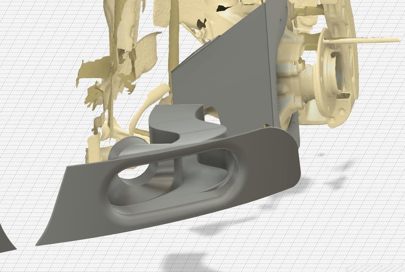 Front duct (gray) modeled in place against the 3D scan (tan) — the oval inlet and outlet drawn to clear the real arm and upright.
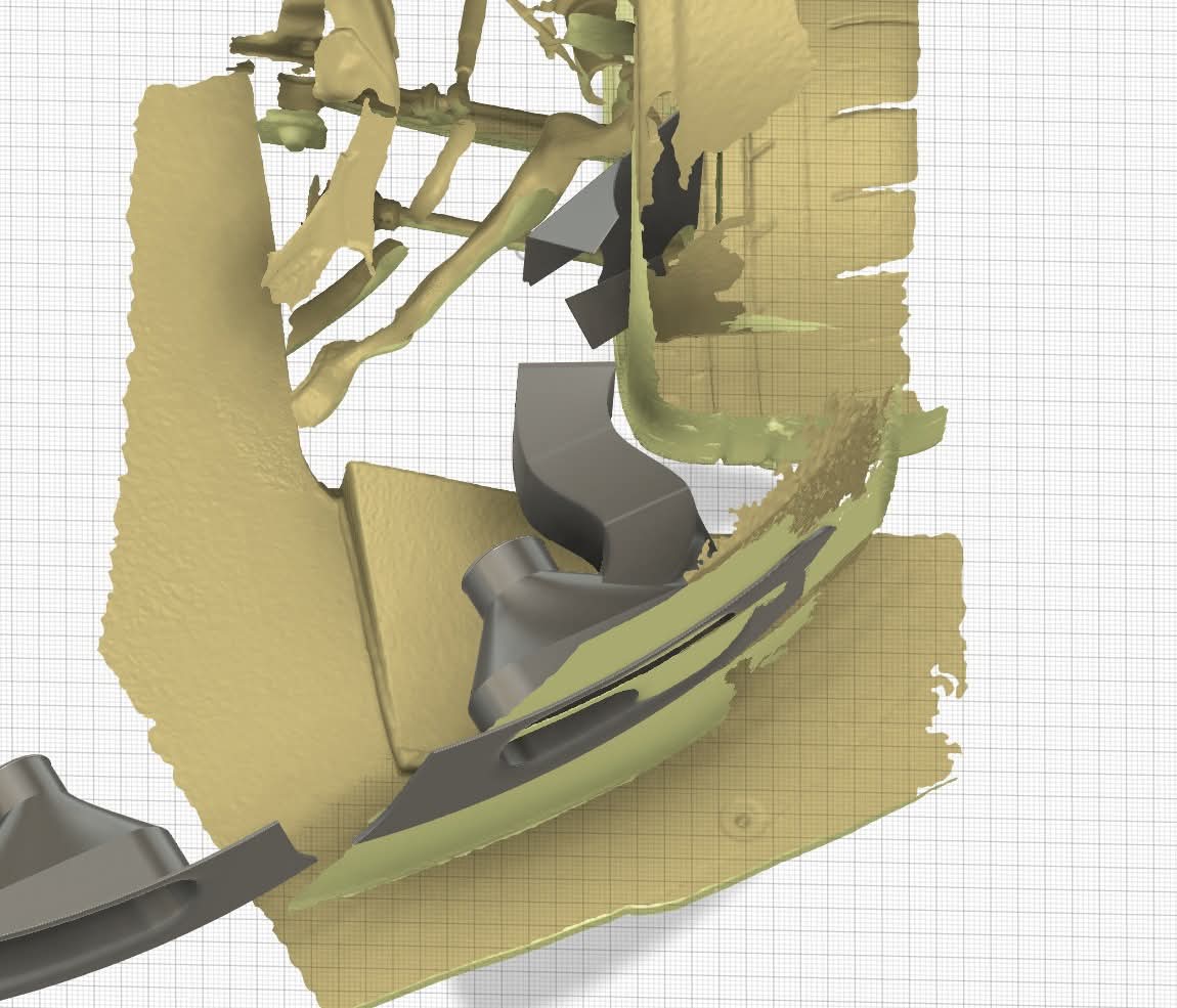 Rear duct routed through the scanned rear subframe and floor — every bend checked against real geometry before anything got printed.
The front duct
The front piece bolts to the lower control arm and puts a scoop out in the airstream ahead of the wheel. Air comes in the mouth, the body necks down, and it dumps straight at the caliper — right where you want it, pulling heat off the pads and the caliper body instead of just spilling past.
The shape borrows from a couple of European brands that have been doing control-arm-mounted brake ducts for years — that’s a proven place to pick up air and a proven way to keep the outlet tracking the caliper. I adapted the idea to the E82’s front geometry rather than copying any one part.
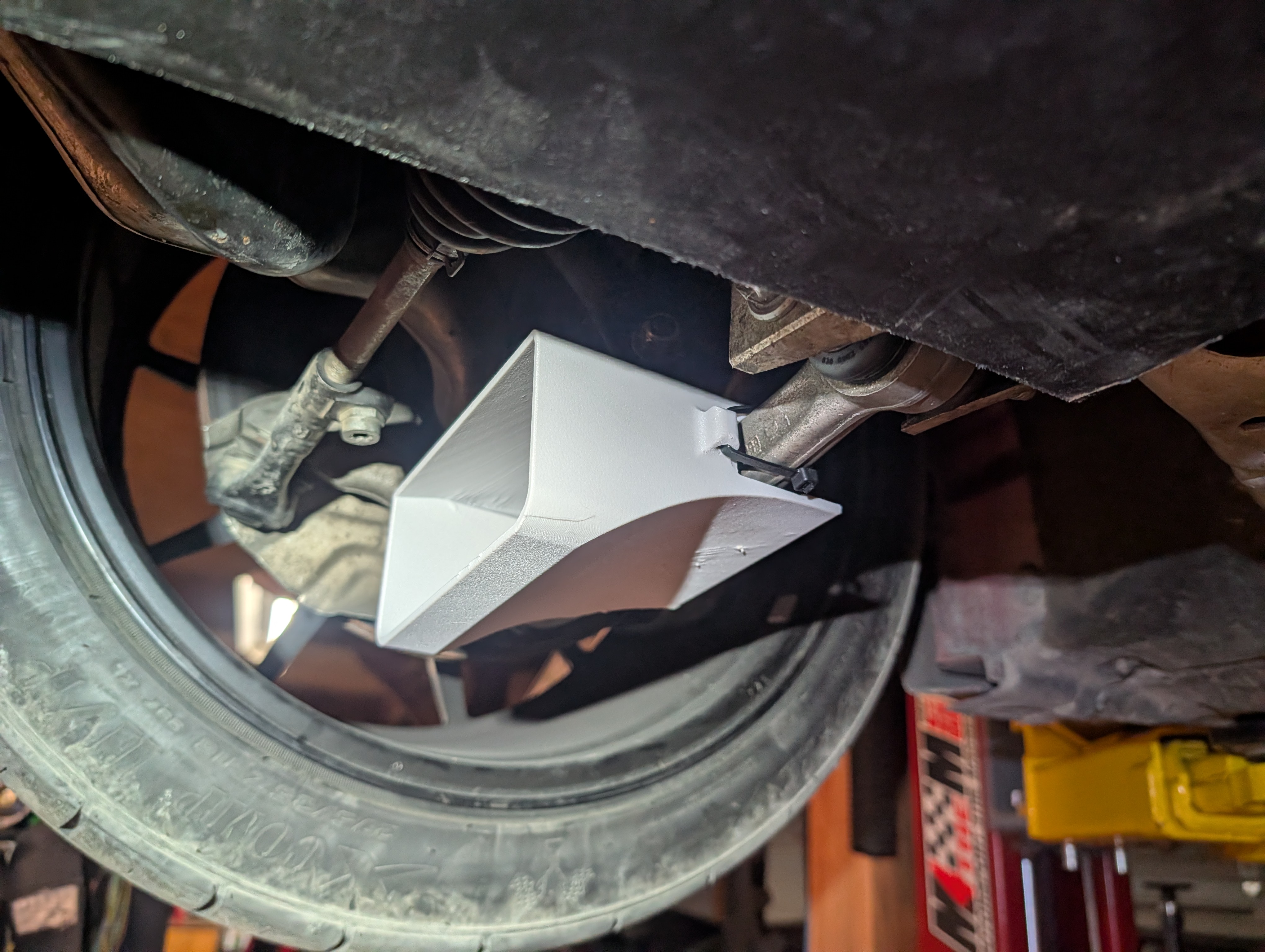 Front duct clamped to the control arm — the mouth sits out in clean air ahead of the wheel.
Mounting it to the control arm instead of the strut or the backing plate means the duct moves with the suspension, so the outlet stays aimed at the caliper through the whole range of travel. It rides on the arm with a strap and the modeled-in saddle, so there’s no drilling into anything structural.
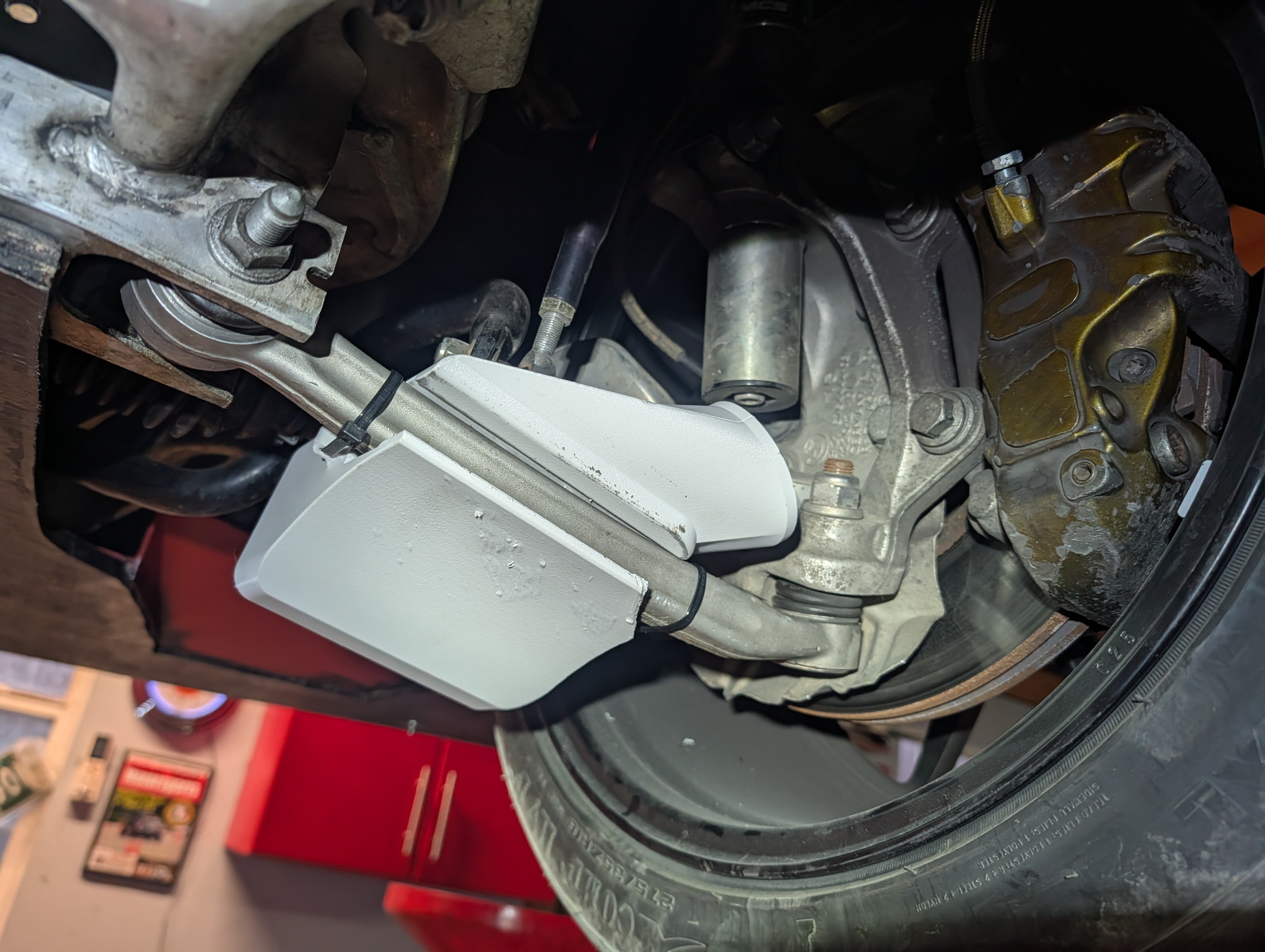 Outlet tucked in behind the wheel, aimed straight at the caliper.
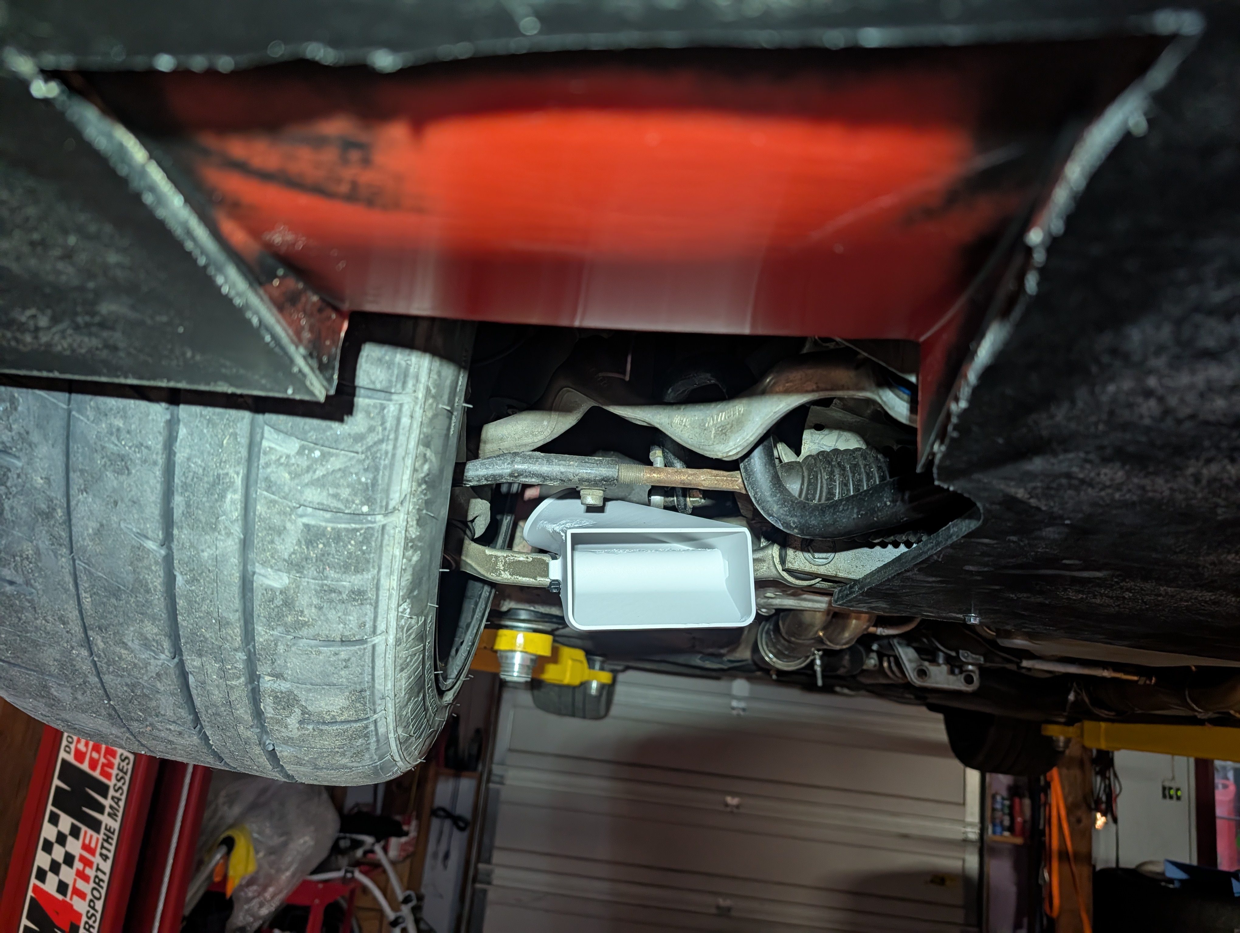 From underneath — the neck-down from scoop mouth to outlet is what accelerates the air onto the caliper.
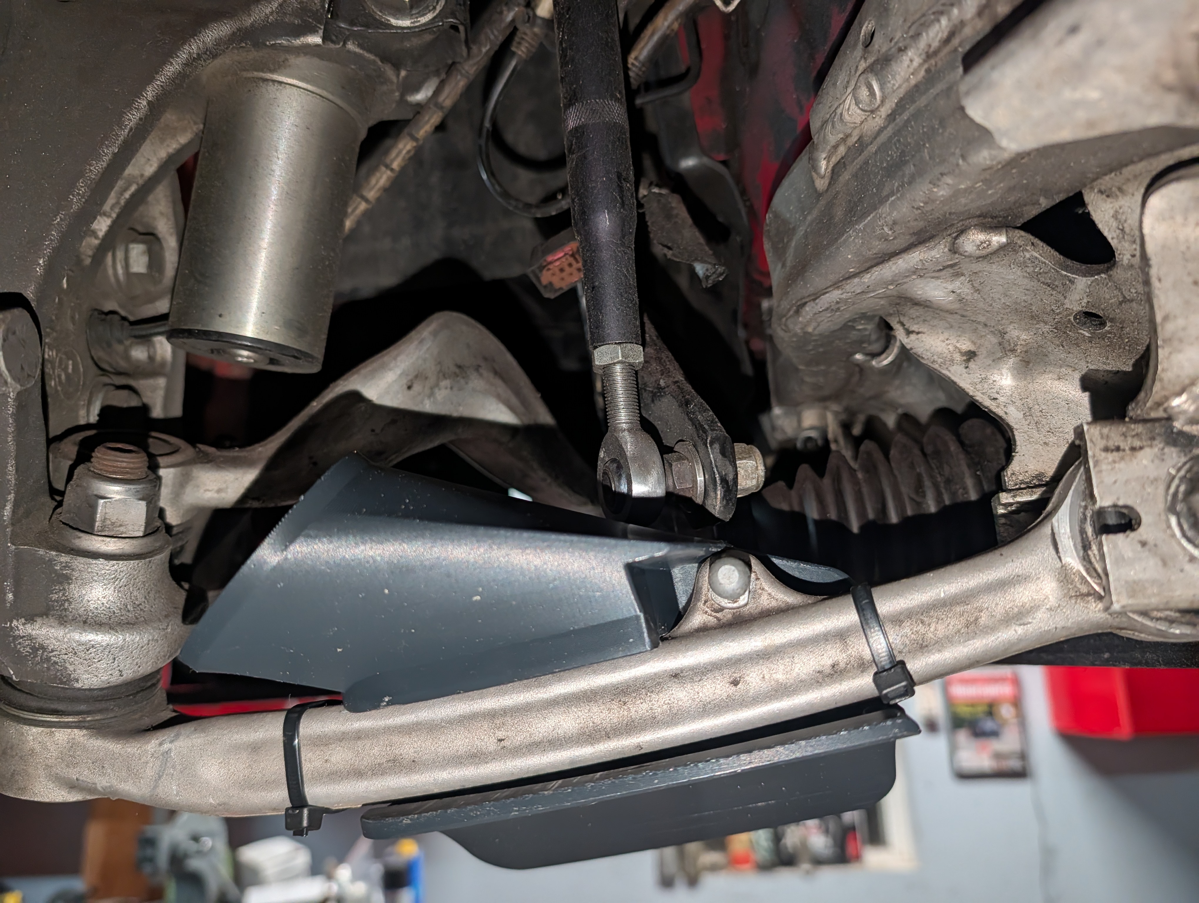 From further back — the front arm duct tucked up on the control arm, clear of the arms and boots through the range of travel.
The rear duct
The rears are the ones I actually cooked, and the factory gives them nothing to work with — no cooling passages at all back there. The rear duct picks up air through a finned inlet mouth and routes it to the rear caliper off the subframe, tucked in among the rear links so it clears everything through travel.
The rear took a lot of influence from the Ford Mustang GTD — the way that car uses a wide finned inlet under the body to feed the rear brakes is exactly the problem I was solving, so the mouth and the sweep of the duct are a nod to it, scaled and reshaped to fit under the 135i.
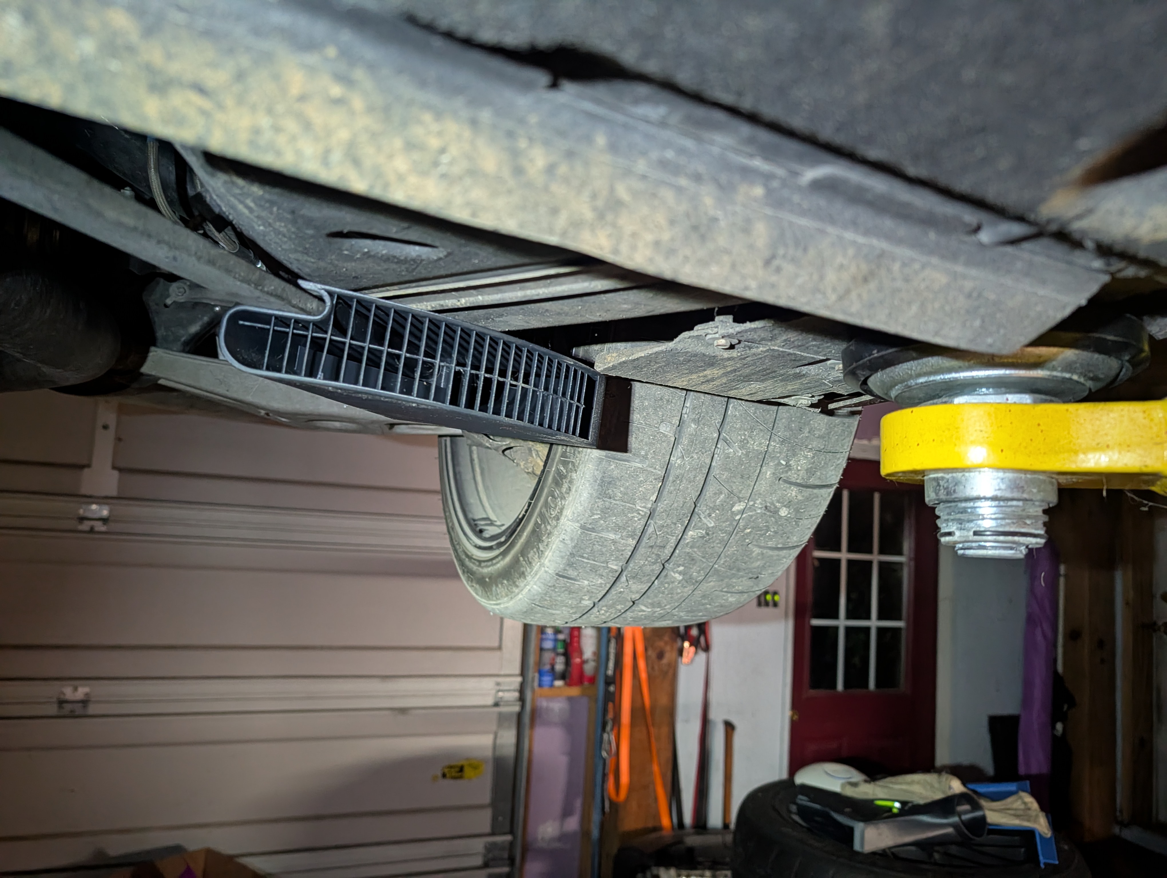 The finned inlet mouth sits below the floor pan, scooping air ahead of the rear tire.
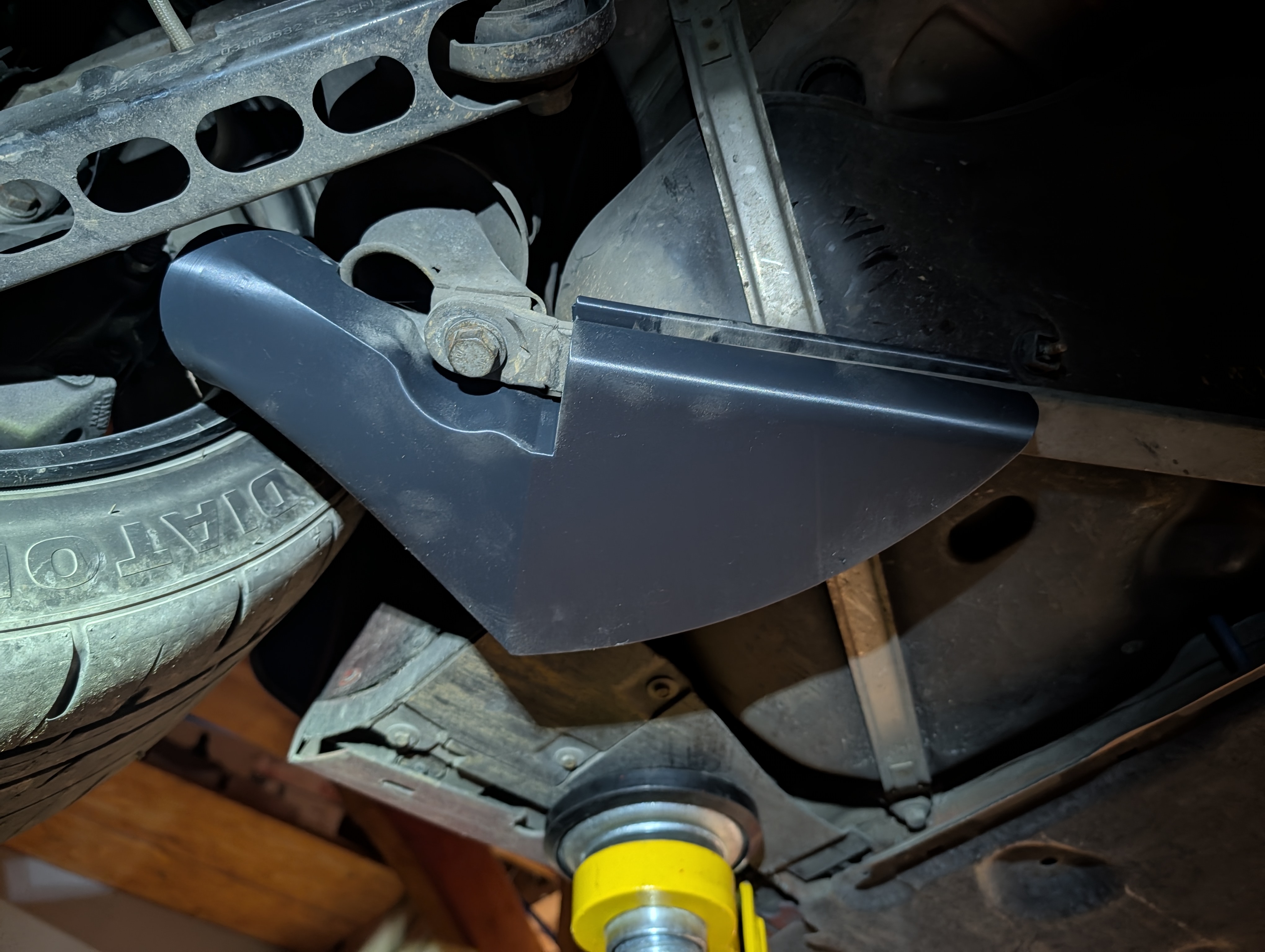 The body picks up on the subframe hardware and sweeps around to aim at the caliper — no brackets to fabricate.
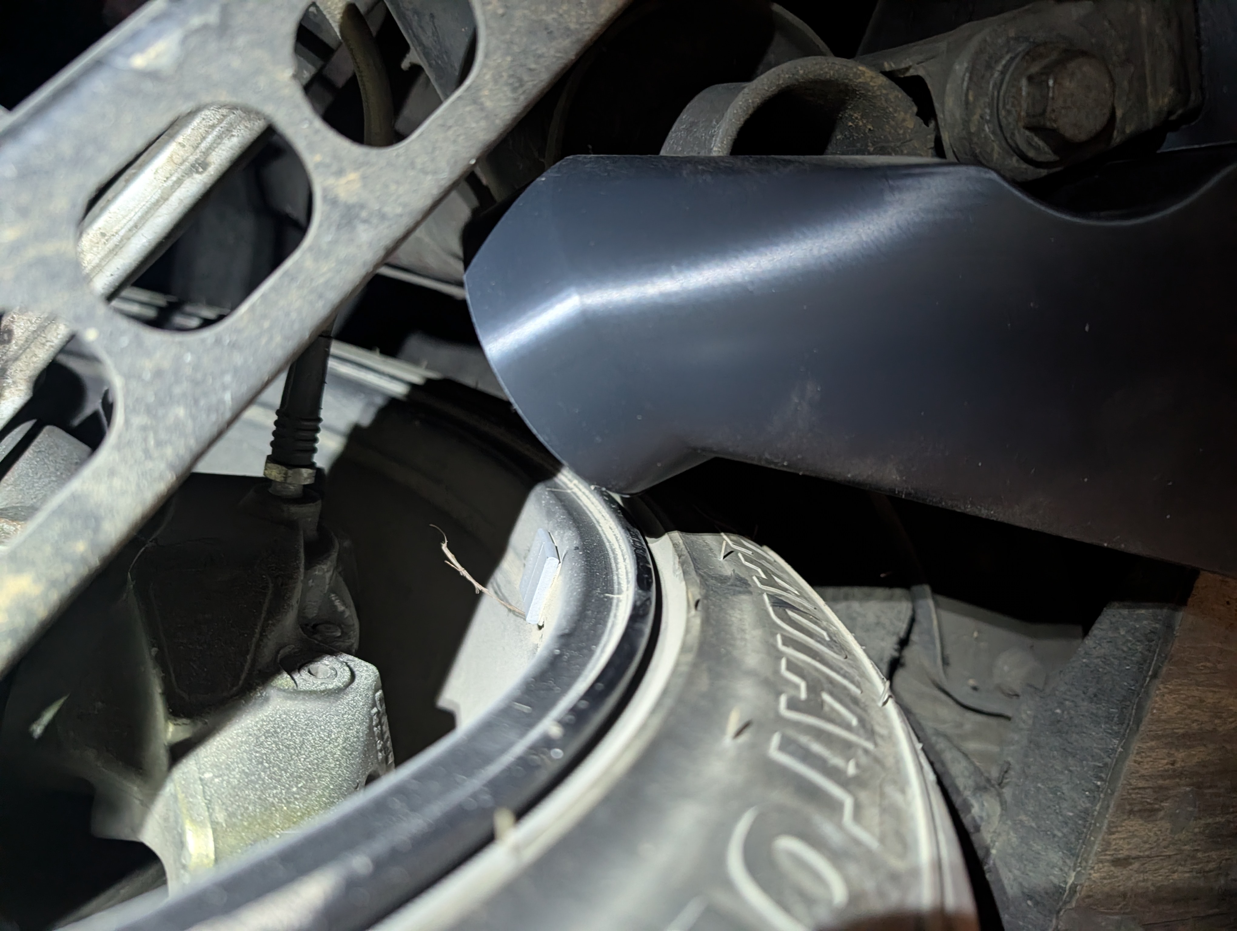 Modeled-in relief lets it clear the mounting bolt and links cleanly.
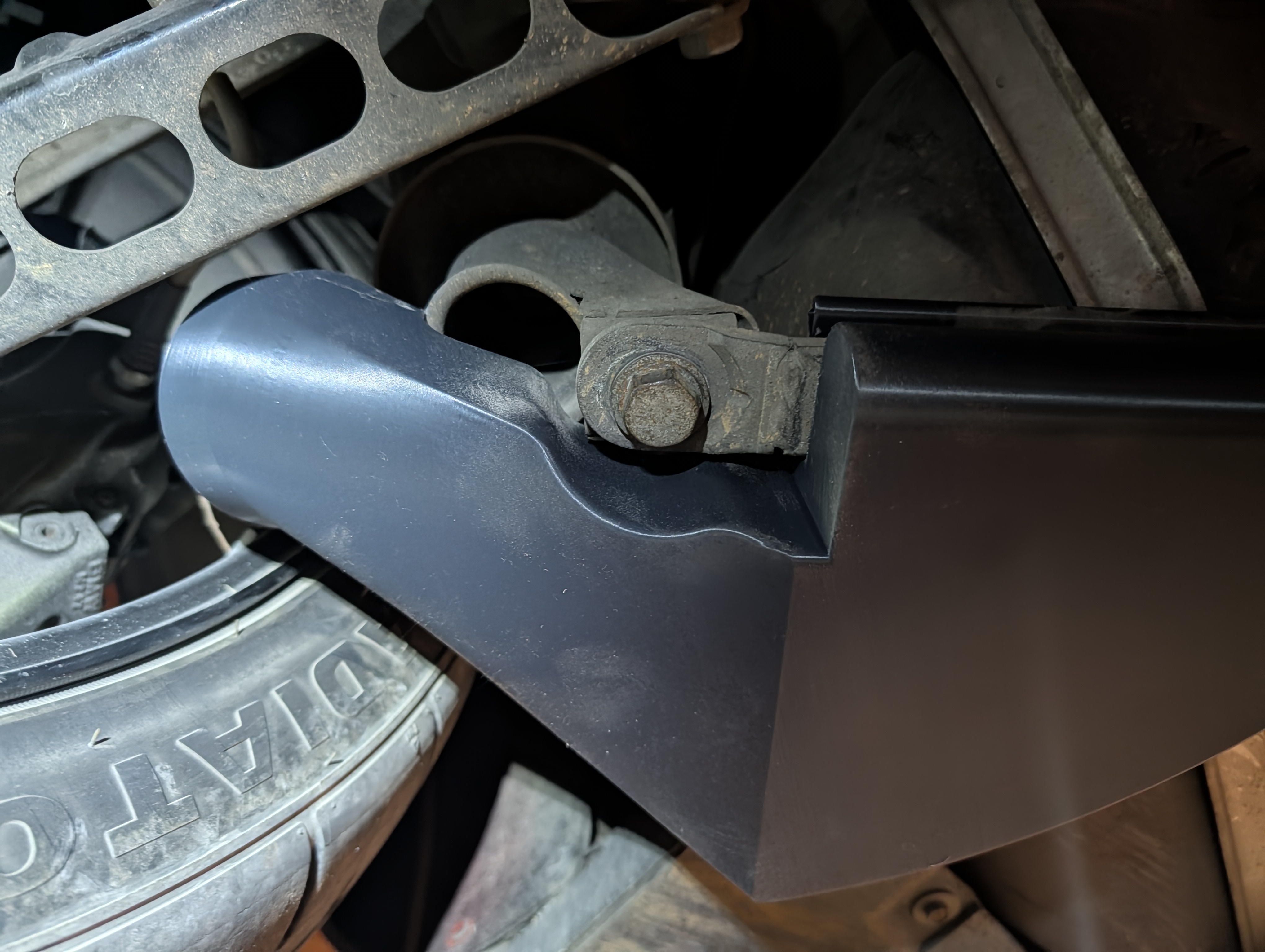 Outlet nozzle pointed straight at the rear caliper.
Air deflectors and bumper overlays
The ducts are only one piece of the front air path. Two more parts finish it: an aluminum deflector at the hub that keeps the delivered air on the rotor, and 3D-printed front bumper overlays at the other end that form the inlet.
Sheet-metal air deflectors
A duct only helps if the air it delivers actually stays on the rotor instead of washing off into the wheel well. So alongside the printed ducts I designed a set of brake air deflectors — aluminum shields that mount at the hub and keep the ducted air channeled across the rotor face. Same as the ducts, these were modeled against the 3D scan so they wrap the hub without fouling the caliper.
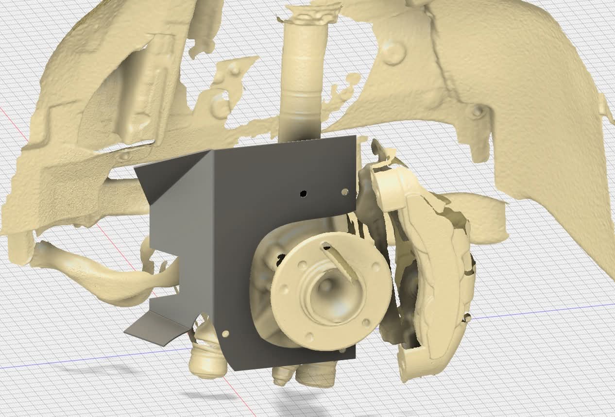 Deflector (gray) modeled over the hub against the scan (tan) — boxed around the back of the rotor with the caliper cleared to the side.
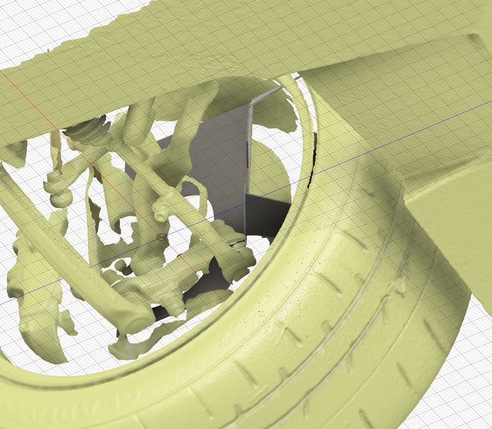 Same part seen from inside the wheel — it shrouds the inboard face so ducted air can’t just spill out.
The final deflector is metal. It comes from Send-Cut-Send as a flat aluminum part, and I bend it to shape myself.
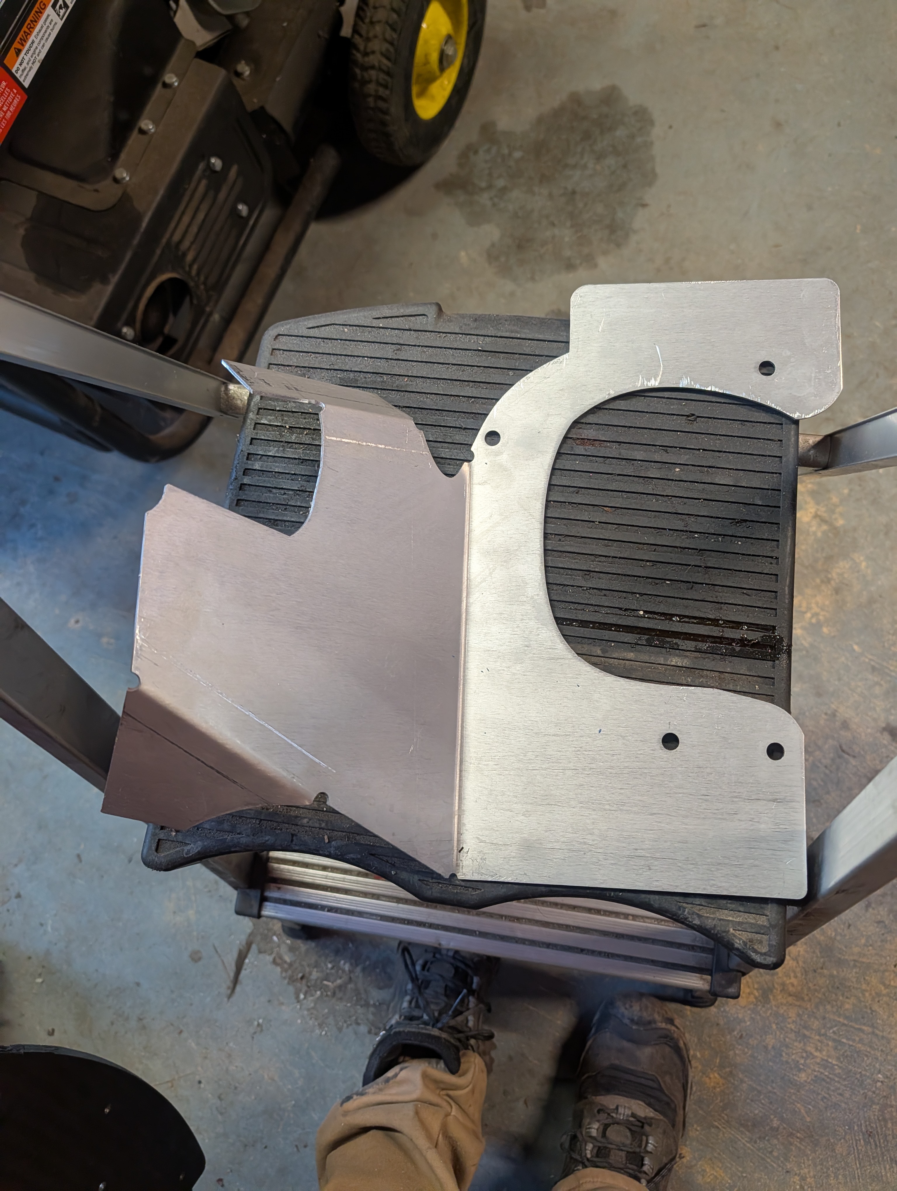 The Send-Cut-Send flat aluminum blank, bent by hand — the big radius clears the hub, the tab forms the air dam, and the holes locate it on the factory hardware.
Before bending any metal, I 3D-printed the deflector in red — partly to check fitment on the car, and partly to use as a bend helper: a former I could bend the flat aluminum blank around to hit the right angles. The red part never sees the car for real; it’s a mockup and a jig.
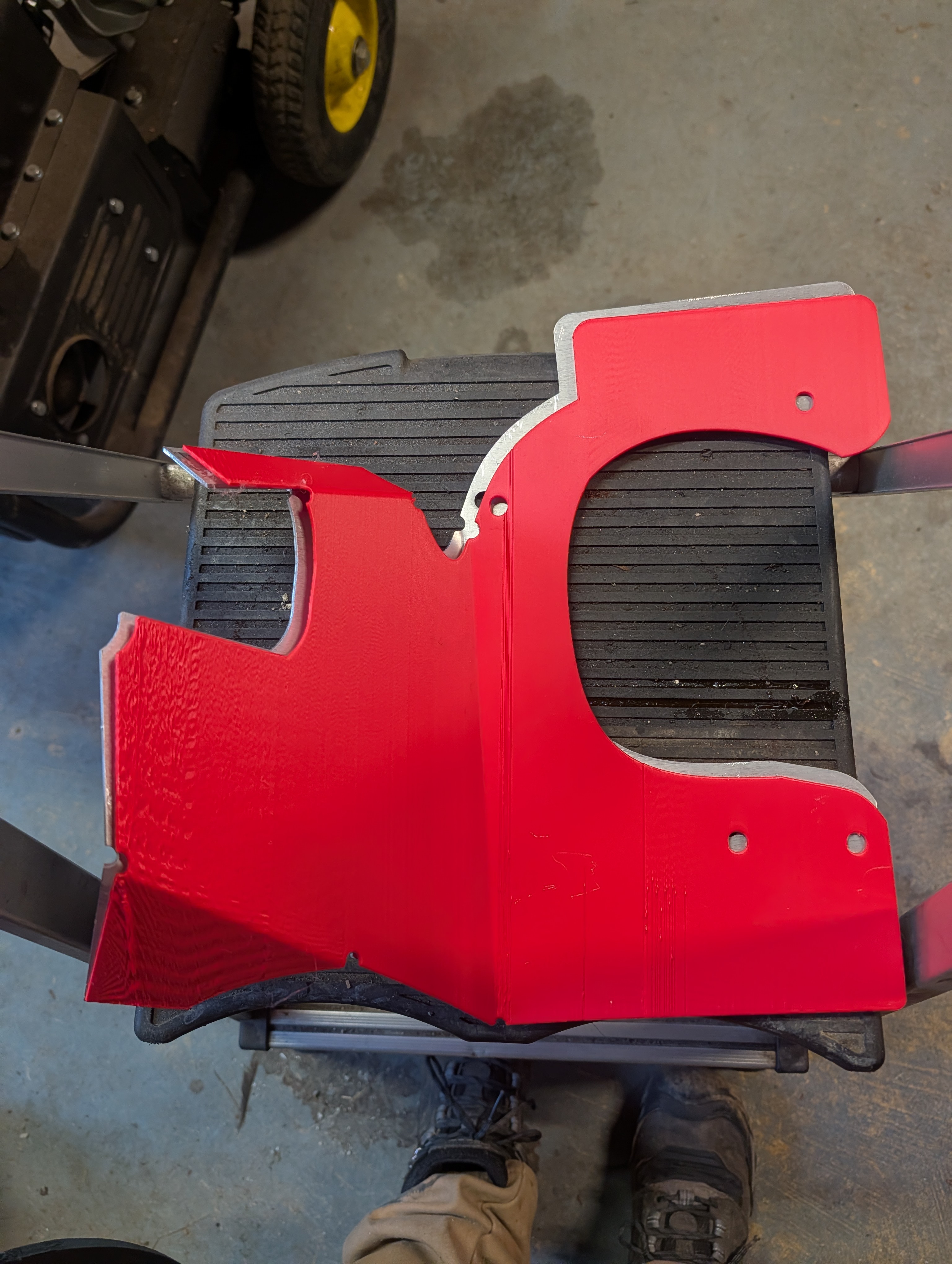 The red one is 3D-printed — a fitment mockup and bending former, not the final part.
Metal makes sense for the part that actually stays on the car, where plastic doesn’t: the deflector sits right up against the rotor in the hottest air. A flat laser-cut blank I bend myself isn’t faster than printing, but it’s convenient, and it’s a metal part that shrugs off the heat next to the rotor in a way plastic never will.
3D-printed front bumper overlays
At the front of the air path are 3D-printed front bumper overlays — they mount into the bumper and form the inlet mouth that catches air and feeds the duct behind it. This is the part that fixes the passive factory passages from the top of the post: instead of dumping air into the wheel well, the overlay gives it a defined mouth pointed at the duct. I run two ports in the overlay, and right now I only use one: the second is blocked off with a yellow plug that I’ve left in for future use, so I can open up a second feed later without re-cutting the bumper.
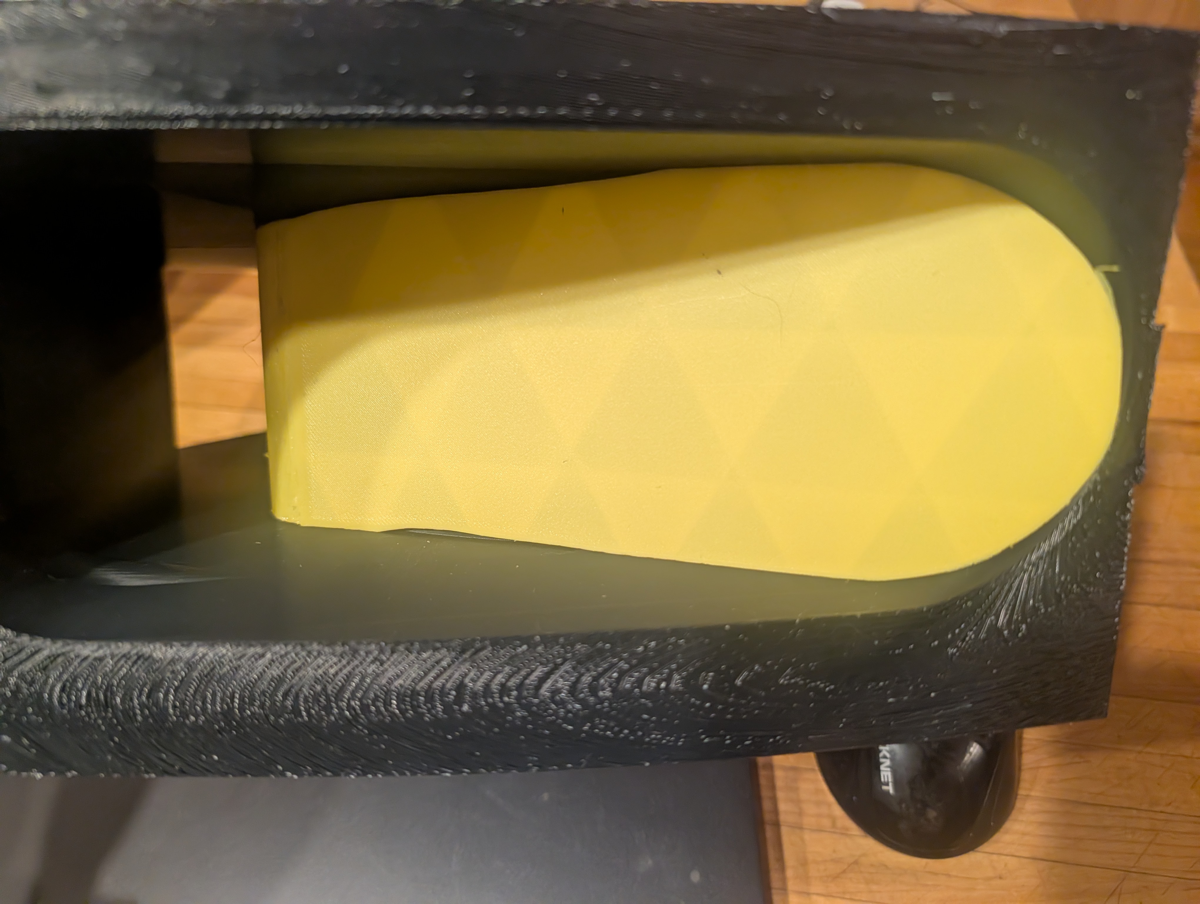 The printed bumper overlay — the yellow plug blanks off the second port until I have a use for it.
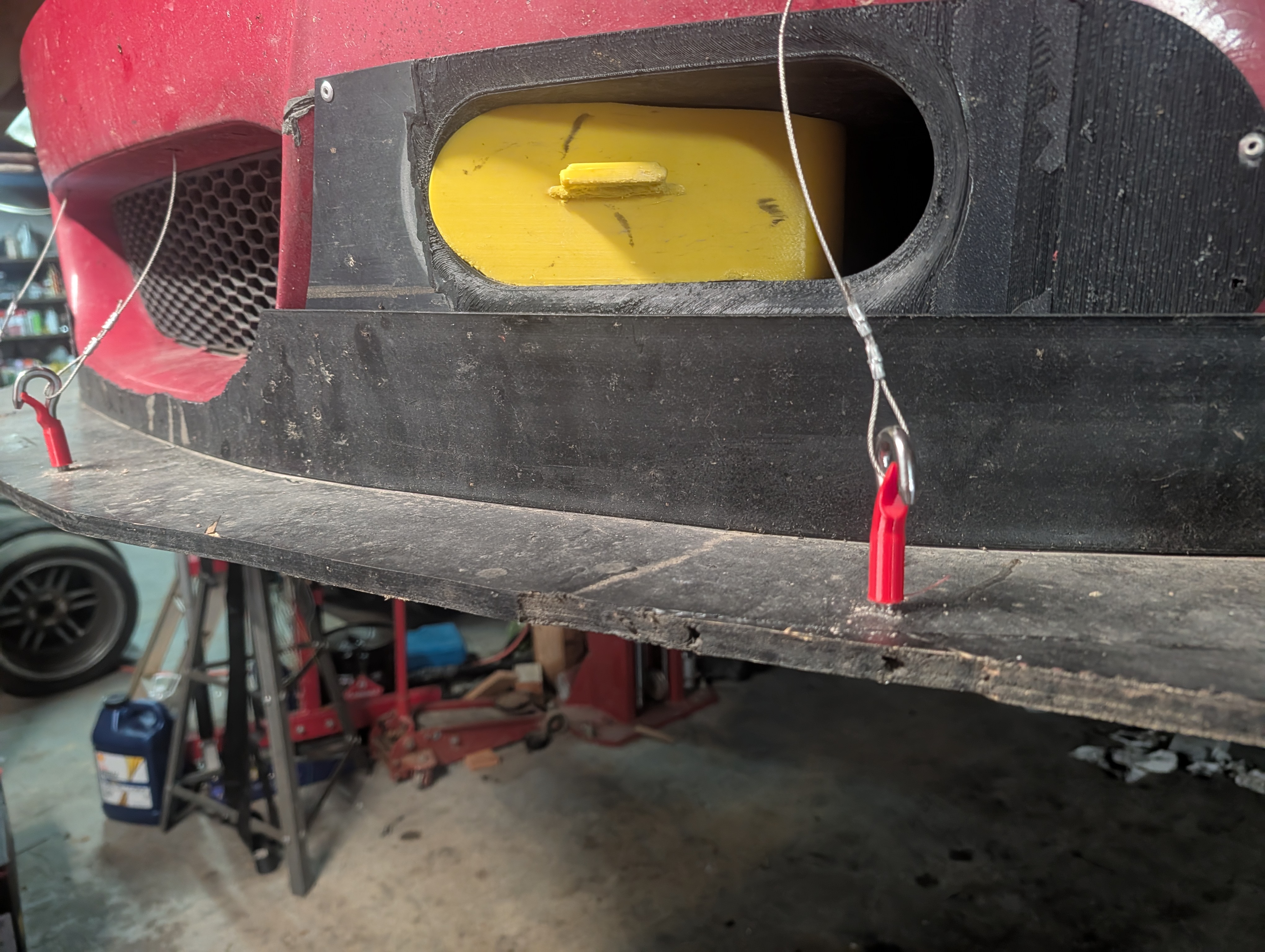 Installed in the bumper — the oval inlet port sits blanked with the yellow plug, ready to open up when I have a use for it.
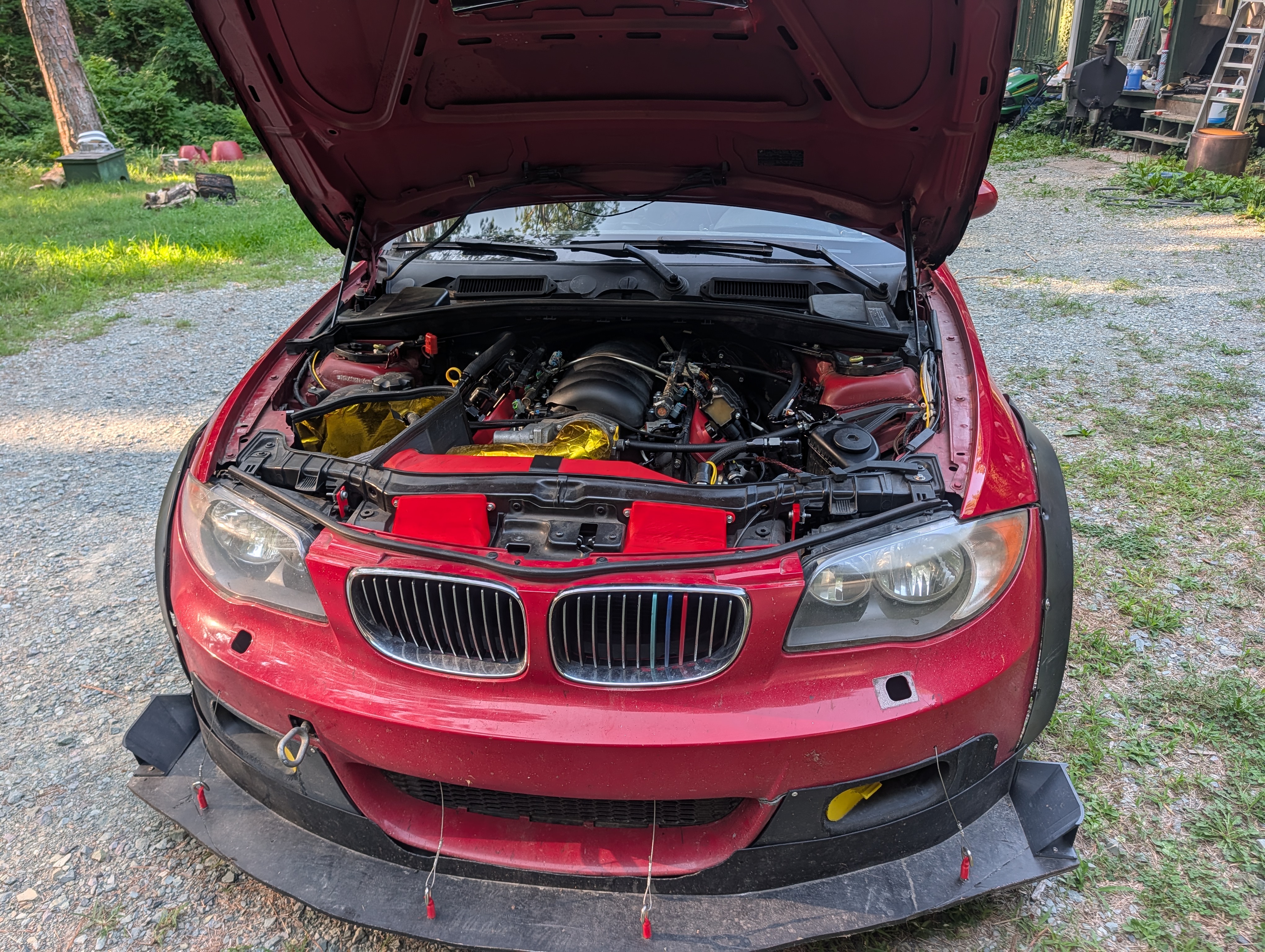 Installed on the car — bumper cover and splitter in place, with the yellow blanking plug visible in the lower opening.
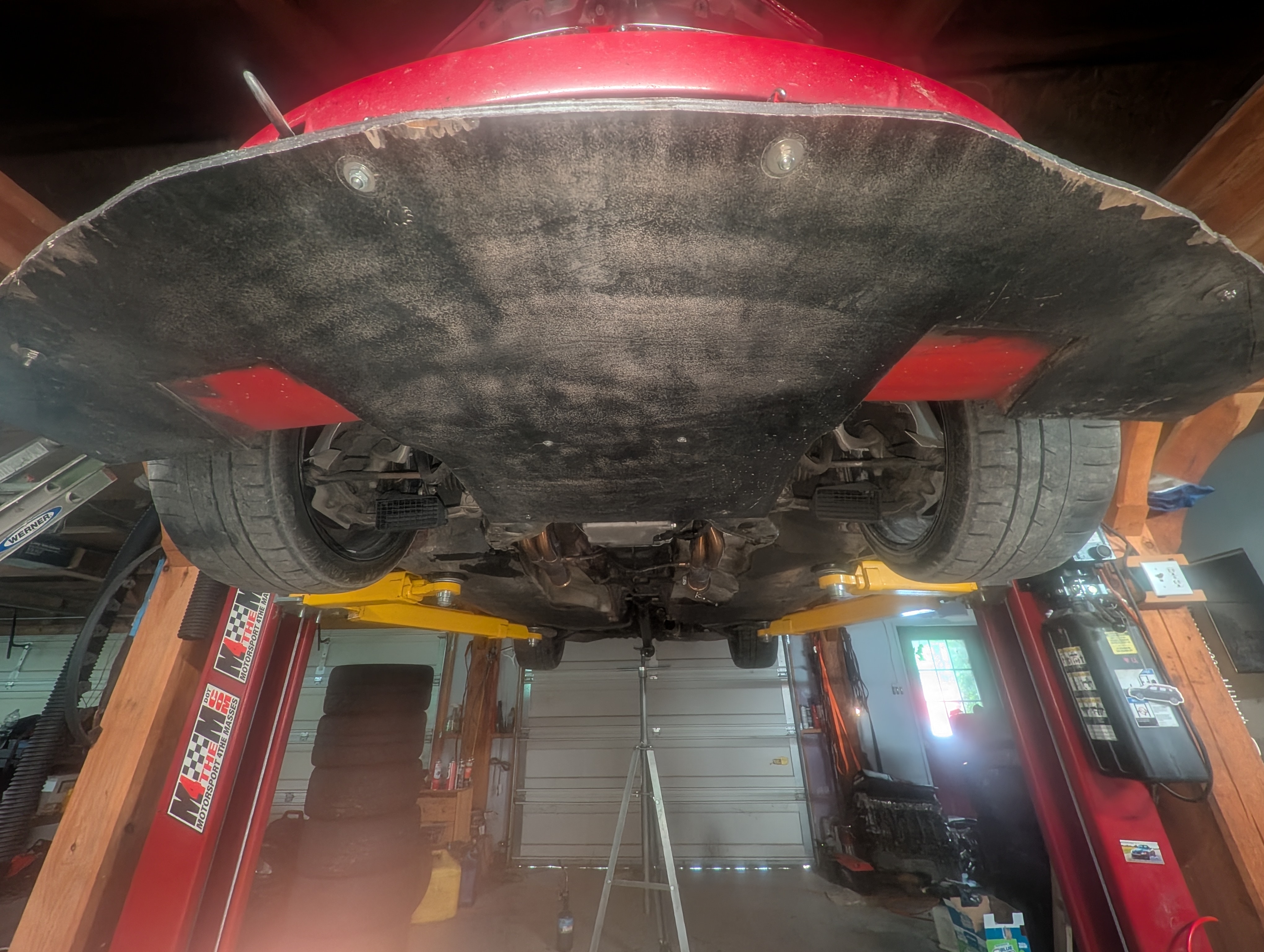 From underneath — the front undertray and splitter that work with the overlays to manage air into the front end.
Printing
Both ducts — and the bumper overlays — print on a Bambu Lab H2S. They live in the airstream under the car — road grime, heat off the rotors, and UV if the car sits — so I run them in a heat- and UV-tolerant blend rather than plain PLA. The front duct is the more involved print thanks to the scoop geometry and the neck-down transition.
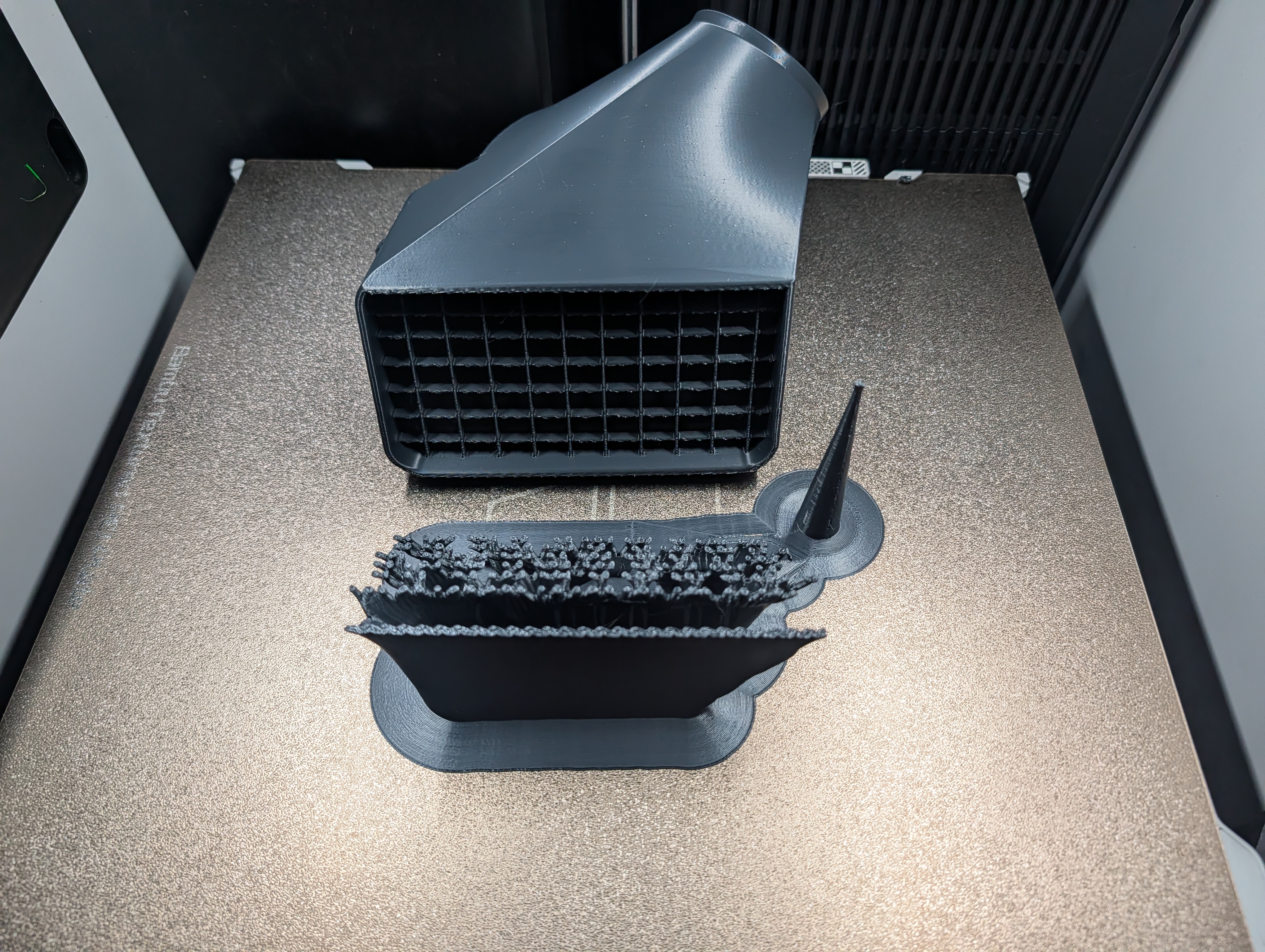 Off the plate — the finished front duct up top, a rear duct with its supports still attached below.
I print them in dark colors that hide brake dust; the white ones in the install photos were an early set I ran to make the geometry easy to see on camera.
Fitment
- Front duct fits the E82 / E88 135i front lower control arm — and shares the arm with plenty of the E9X family, so it carries across a lot of the 3-series too.
- Rear duct fits the E82 rear subframe.
- Both mount with straps / zip ties and the modeled-in saddles — no drilling into anything structural.
- Takes standard 3” brake duct hose if you want to run air to the mouth from a bumper inlet, or run them as-is scooping from inside the wheel well.
- Wheel clearance: fits under 17×10 and 18×10 wheels.
How it’s worked out
Short version: it works, maybe too well. The cooling is significant enough that it has noticeably extended pad and rotor life — the whole reason I built it.
The one trade-off is that with this much air on the brakes, they can squeak a lot on tracks without heavy braking zones — somewhere like NCCAR, where the brakes never really get up to temperature, the pads stay cold enough to talk back. On a track with real braking zones that goes away.
And the failure that started all this: I’d had the ceramic caliper piston tips fail, front and rear, from heat. With this cooling in place, that won’t happen again.
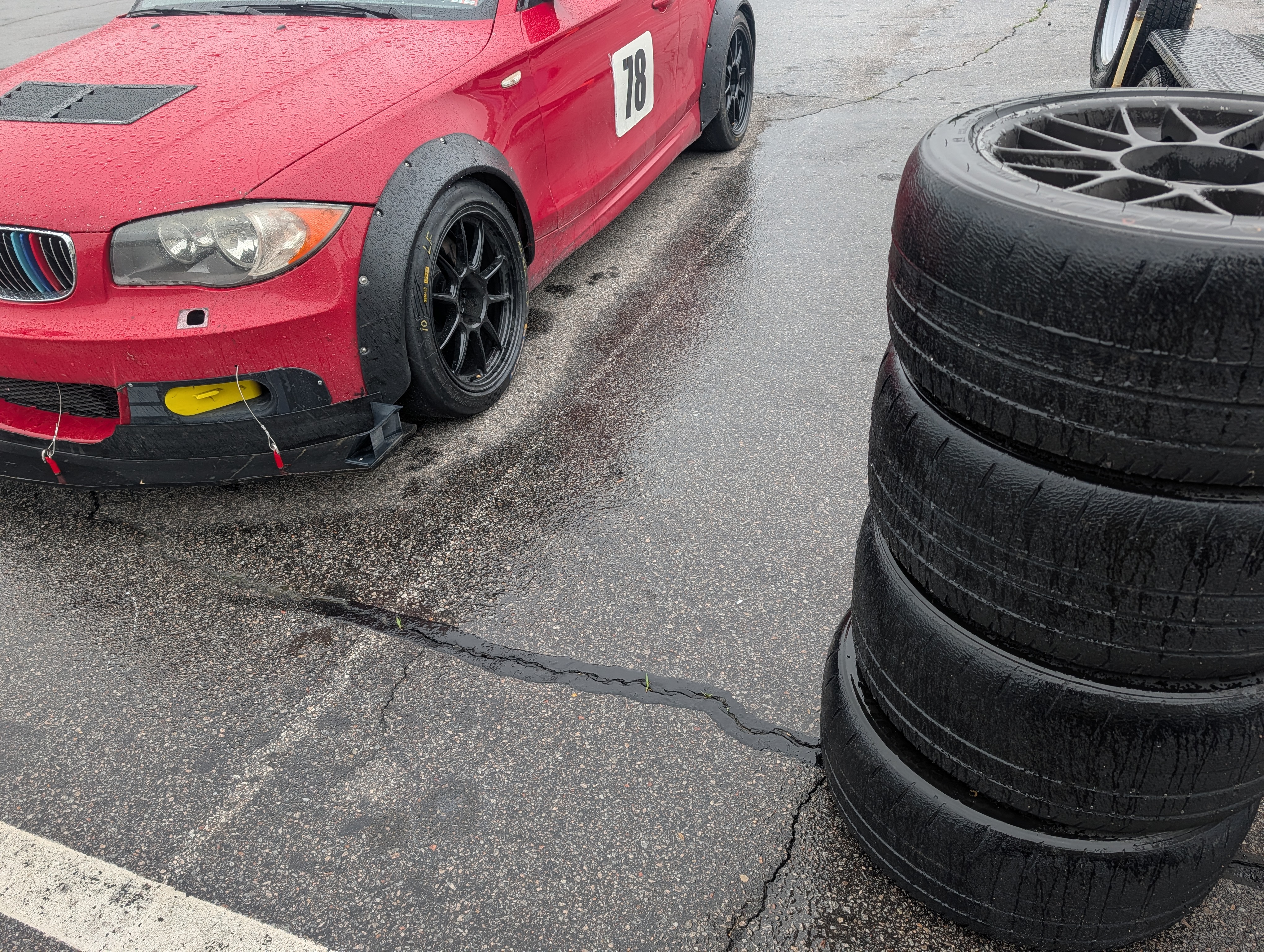 The car it all serves — #78 out at a wet weekend, front splitter and bumper overlays doing their job.
#78 on track — the ducting earning its keep.
The fine print
- Track use only.
- No warranty — it’s a printed plastic part living under a moving car near hot brakes. Inspect it at every event like you would any other duct or heat shield, and re-check the straps.
Where to buy
Two ways to get them: I’ll print you a finished set, or you can print your own from the STLs.
Printed parts
Printed to order on a Bambu Lab H2S, priced per pair (both sides of the axle):
| Part | ASA | PAHT-CF |
|---|---|---|
| Front pair (both sides) | $100 | $120 |
| Rear pair (both sides) | $150 | $175 |
| Full car (front + rear) | $250 | $295 |
ASA is the standard UV-stable choice; PAHT-CF is the black, maximum-heat-resistance option. Shipping billed at actual cost. DM me on Instagram — @mattryan6729 — with the pair(s) and material you want and I’ll quote shipping to your zip.
Print it yourself
STLs on Cults3D:
| Part | STL |
|---|---|
| Front control-arm brake cooling duct | View on Cults3D |
| Rear brake ducts | View on Cults3D |