Factory piece against my snout, rear port closed and open
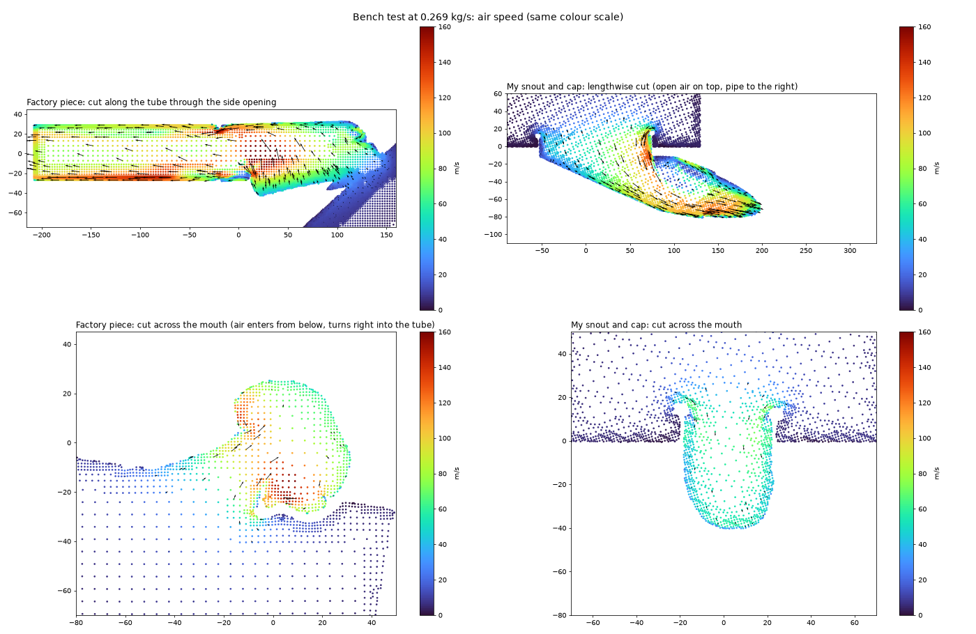
Four versions of the same R53 intake at the airflow a 240 whp car needs: the factory front piece, my printed snout, and my snout with two sizes of rear port cut in the airbox. The numbers below are the vacuum ahead of the throttle body. Lower is better.
The four cases
Same tube, same airbox, same filter, same airflow: 0.269 kg/s, about 474 CFM. Only the front piece and the rear port change.
| Factory piece, rear port closed | My snout, rear port closed | My snout, 3-inch rear port | My snout, 6 × 4.2 inch rear port | |
|---|---|---|---|---|
| Vacuum ahead of the throttle body | 20.7 kPa 3.00 psi | 14.4 kPa 2.09 psi | 6.6 kPa 0.96 psi | 5.9 kPa 0.85 psi |
| Total pressure lost in the intake | 15.99 kPa | 9.75 kPa | 1.94 kPa | 1.27 kPa |
| Air through the front piece | 100% | 100% | 29% | 11% |
| Air through the rear port | none | none | 71% | 89% |
- Factory piece to my snout, rear port closed: 6.3 kPa less vacuum (0.91 psi).
- Cutting a 3-inch rear port: another 7.8 kPa less (1.13 psi).
- Opening that up to 6 × 4.2 inches: 0.7 kPa more (0.10 psi). Most of the gain is in the first cut.
Every arrow is traced through the solved velocity field and moves at the local air speed, slowed 250 times. All four use the same colour scale, 0 to 120 m/s.
What was compared
Both front pieces sit in the same slot in the radiator support and slip onto the same printed snorkel tube. Everything behind them is identical.
- My snout. The front piece from my cold air intake tube: a 131 mm slot mouth that funnels into a 66 mm socket, with a snap-on cap. The opening through the cap is 3,816 mm².
- Factory front piece. The part my snout replaces. Its inlet is a shallow tray that fills the same slot; the air turns sideways through an opening about 24 mm tall into a tube whose bore runs from 1,800 to 2,600 mm².
- Rear port. The printed airbox leaves the factory partition for you to cut, so the rear port is as big as you make it. Closed means the partition is intact.
- The rest of the tract. The 61 mm printed tube, the factory lower box and the airbox with a dry cone filter, out to the throttle body.


How it was modelled
- One piece of air. From still air above the radiator support, through the front piece, tube, lower box, filter and housing, to the throttle body end. About 1.16 million cells per run in OpenFOAM, steady flow, k-omega SST.
- Airflow. 0.269 kg/s, what a supercharged 1.6 needs for about 240 whp. That is a target, not a dyno sheet.
- Filter. A porous layer set to 500 Pa at this flow. That figure is assumed, not measured.
- Factory piece. Rebuilt from my 3D scan of the part. The scan caught 64% of the inside wall; for the rest I took the outside and subtracted 2.8 mm of wall, the thickness measured where both sides were scanned.
- Vacuum and loss. Vacuum is the static pressure below atmosphere at the throttle body end. Loss is the total pressure given up on the way there. About 4.6 kPa of the vacuum in every case is not a loss: it is the speed of the air itself, leaving through the 61 mm outlet at around 76 m/s.
Factory piece against my snout
With the rear port closed, all the air has to come through the front piece, so this is where the two differ most.
Print it yourself
Both parts are STLs on Cults3D: the cold air intake tube with the snout, and the airbox you cut the rear port in.
Get one printed
No printer? I print the snout and tube in ASA, any colour, for $125, or in PETG for $80, plus shipping (generally $20 or less), and the airbox to order in glass- or carbon-filled filament. Email ryan3ddesigns@gmail.com with the part and colour. Prices and materials.
| Factory front piece | My snout | |
|---|---|---|
| Lost by the time the air reaches the lower box | 10.5 kPa | 4.9 kPa |
| Front piece alone on a bench | 9.41 kPa | 3.05 kPa |
| Bore at the neck | 57.9 mm equivalent | 61.4 mm |
| Opening into the part | about 2,880 mm² | 3,816 mm² |
| Peak air speed on the bench | 207 m/s | 149 m/s |
The factory piece costs about 6 kPa more than my snout, and two tests agree on that: 6.2 kPa in the whole tract and 6.4 kPa on a bench, where each part breathes still air and blows into a straight pipe. Nearly all of it is lost inside the front piece itself.
It is not a bad shape. It is a small one, sized for a stock engine and a quiet cabin. At roughly stock airflow, about 0.15 kg/s, the same bench test would put it near 3 kPa, because loss goes with the square of the flow.
What the rear port does
With the port closed, every bit of air goes through the snout and the 61 mm tube at 60 to 100 m/s. Cut a 3-inch port and 71% of it comes in at the back instead, so the tube only carries about a third of the flow and its losses nearly vanish. The loss in the intake falls by 80%, from 9.75 to 1.94 kPa.
Once the port is cut, the front piece matters much less: it is only carrying a third of the air or less.
The new curved-top airbox
The airbox now has a curved, egg-shaped roof that takes much less filament to print. I ran it through the same model with my snout and all three rear ports. Only the roof changes.
| Rear port closed | 3-inch rear port | 6 × 4.2 inch rear port | |
|---|---|---|---|
| Vacuum ahead of the throttle body, original top | 14.4 kPa | 6.6 kPa | 5.9 kPa |
| Vacuum ahead of the throttle body, curved top | 14.2 kPa | 6.5 kPa | 5.9 kPa |
| Total pressure lost, original top | 9.75 kPa | 1.94 kPa | 1.27 kPa |
| Total pressure lost, curved top | 9.52 kPa | 1.89 kPa | 1.30 kPa |
| Air through the rear port, curved top | none | 70% | 88% |
Every difference is about 2%, inside the 3 to 5% these runs wander, and they don’t all go the same way. In this model the curved top flows the same as the original. The curve takes 0.33 litres of air out of the housing, all of it above the sides of the filter, where the air barely moves. The loss across the housing itself, from the lower box to the throttle body end, is 2.93 kPa against 2.95 for the original top. The filter still clears the roof by at least 21 mm, against 27 mm before.
The curved top’s shape comes from its Fusion 360 model as a fine surface mesh, fitted into the same model as the original housing to within about 2 mm.
What I tried that did not beat it
I also ran reshaped snouts through the same model: a mouth that fills more of the slot, a rounded inside corner, and a bell-shaped lip on the cap. They came out between 10.2 and 11.4 kPa of loss, against 9.75 for the snout as it is. So the snout stays. What does change is the cap: a new one that reaches down to the radiator support and grips the outside of the mouth, which costs no flow in the model. It is not printed yet.
What this does not show
- No car around it. The air starts as a still box above the radiator support. There is no bonnet, grille or road speed.
- Speed. Above 200 m/s the model is out of its depth, because it treats air as incompressible. The real factory piece would do worse at this flow, not better.
- Run-to-run wander. My snout’s runs wander 3 to 5%, so differences under about 0.5 kPa mean nothing. The factory gap is twelve times that.
- Not horsepower. These are pressures in a simulated intake, not a measurement on the car. The pressure CAN node is a board I've designed to measure them; it isn't built yet. Two of its sensors read to 40 kPa, enough for every case here, port closed included; the most vacuum in these runs is about 21 kPa. The four 10 kPa ones suit shorter stretches, like either side of the filter.