Pressure CAN node
Six pressure sensors and eight 0–5 V inputs on one board. It reads all fourteen and puts them on the car's CAN bus a hundred times a second, so the data logger records aero, intake and cooling pressures alongside everything else.
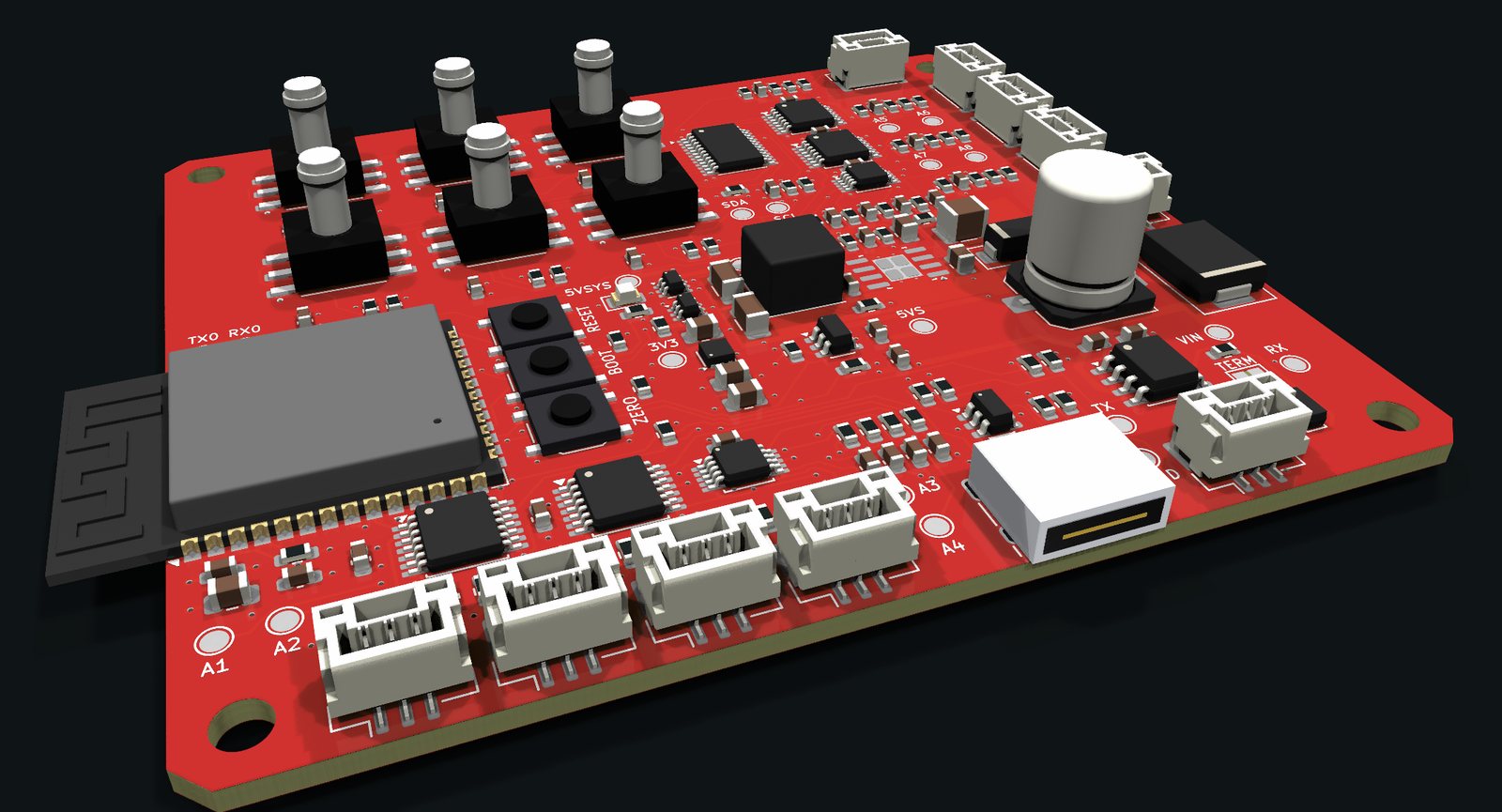
What it measures
Each sensor has one hose barb and reads the pressure there against the air inside the node's box, below it as well as above. Four read to 10 kPa for aero and cooling; two read to 40 kPa for the vacuum a turbo pulls at its inlet. A drop across a part is two channels subtracted. How to fit them.
Pressure taps on the splitter, underbody, diffuser or wing: how hard the floor sucks at speed and what each surface sees. Dynamic pressure is about 0.5 kPa at 100 km/h and 1.9 kPa at 200 km/h.
Vacuum before and after the air filter, on the two 40 kPa channels. The difference is the filter's restriction, and the second reading is what the turbo sees. A restrictive filter can pull 5 to 7 kPa at full flow, and a turbo inlet more.
Pressure at the cowl and on both faces of the radiator. The drop across the core shows how much air actually goes through it.
For sensors you already have: oil or fuel pressure senders, a spare MAP sensor, ride-height pots, or a tap on an ECU sensor's signal. Each connector carries a switched 5 V supply. Remove its link when tapping a sensor the ECU already powers.
The board
Everything is surface mount and placed by the board house, the pressure sensors included.
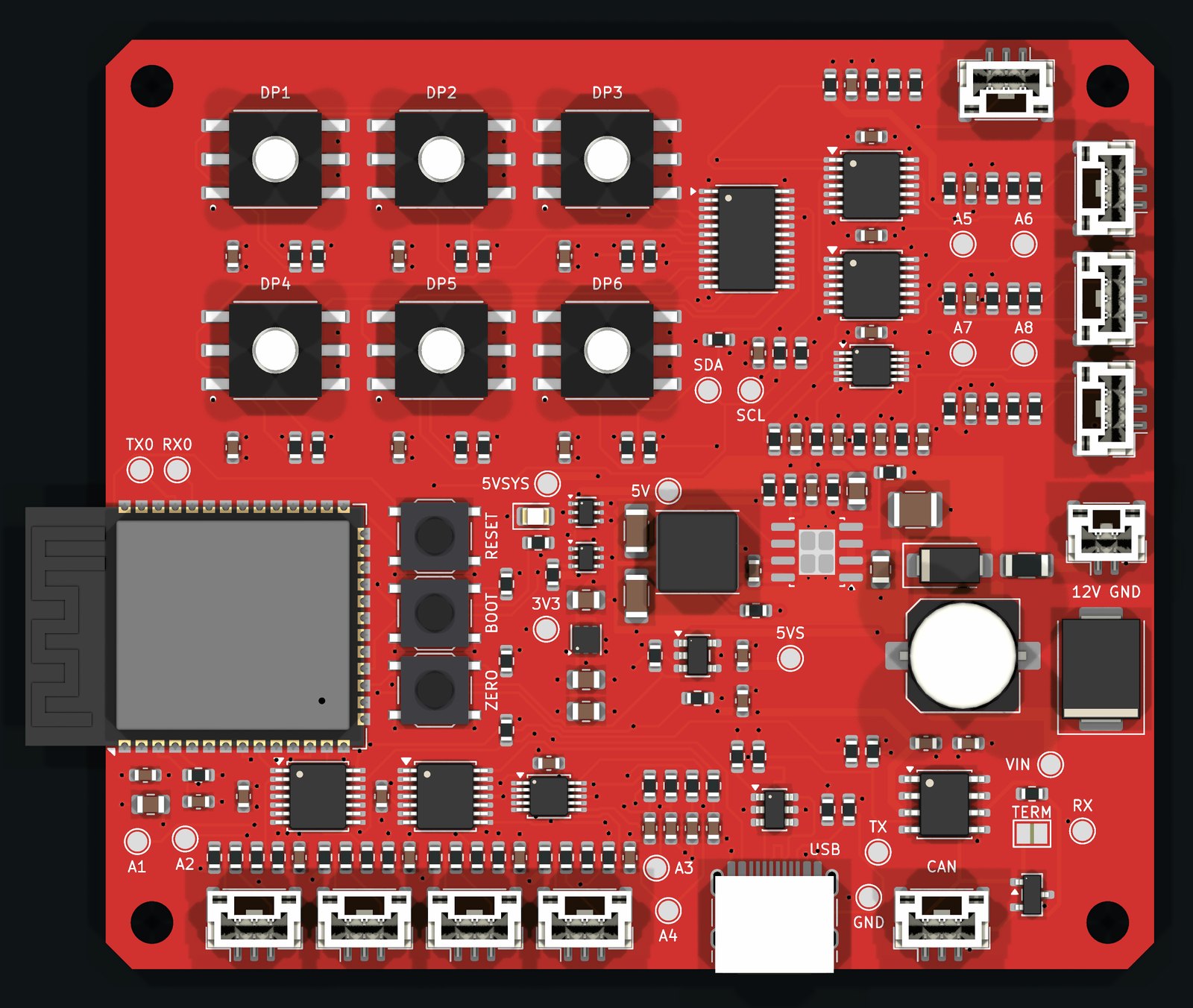

How it works
Switched 12 V comes in through a 1 A fuse and a reverse-battery diode, with a 33 V TVS for load dump. An LM5164 buck makes 5 V. Two ideal diodes choose between that and USB, with the car's side first, so the board runs on the bench from a laptop, stays up when both are plugged in, and the two supplies never feed each other. A 3.3 V LDO runs the logic.
All six sensors have the same I2C address, so a TCA9548A switch puts each on its own branch and the ESP32-S3 reads them in turn. A reading only counts once the sensor says its conversion finished, and a sensor that stops answering drops out without stalling the others. ZERO averages 100 readings from every channel and subtracts them. Press it with every port open to the same air before a run.
Each input goes through a divide-by-five divider (500 kΩ to ground, so it barely loads an ECU signal), an isolation switch that stays open until the firmware is running, a buffer and a 16-bit ADC; AIN1–4 and AIN5–8 have one ADC each, converting side by side. A 12 V short on an input only puts 2.4 V on the switch.
The 5 V on the analog connectors comes off the buck through a 500 mA current-limited switch. It's only there with the car's power on, never from USB alone, and a fault turns it off.
On the CAN bus
A TCAN1042 transceiver sends five 8-byte frames every 10 ms and a status frame every 100 ms, at 500 kbit/s. The IDs and bitrate are firmware settings. A channel that stops updating, isn't fitted, or reads past its range is flagged invalid in its frame instead of repeating its last value. The 120 Ω terminator is off unless you bridge TERM on the board at the end of the bus.
| ID | Contents |
|---|---|
| 0x520 | DP1–DP3 in Pa (signed 16-bit), valid bits, frame counter |
| 0x521 | DP4–DP6 in Pa, valid bits, frame counter |
| 0x522 | AIN1–AIN4 in mV, 0 to 5,250 |
| 0x523 | Health: protocol version, counter, valid masks, power and zero flags, uptime |
| 0x524 | AIN5–AIN8 in mV |
| 0x525 | Status, ten times a second: fitted, overrange, zeroed and fault masks, bus recoveries |
Fitting it to a car
Each channel is one hose: a tap where you want the pressure, run back to the node. Every sensor reads its hose against the air inside the node's box, so most of the work is deciding what that air is, and the hose runs.
The taps
Plumbing the six channels
| Sensor | Range | Port | Reads |
|---|---|---|---|
| DP1 | 10 kPa | Pitot-static, tip | Dynamic pressure, so airspeed and headwind |
| DP2 | 10 kPa | Front floor tap | Suction under the front of the car |
| DP3 | 10 kPa | Diffuser tap | Suction under the back |
| DP4 | 10 kPa | Cowl, base of the windscreen | Whether the cowl really is high pressure |
| DP5 | 40 kPa | Airbox, before the filter | Depression ahead of the filter |
| DP6 | 40 kPa | Airbox outlet, toward the turbo | Depression the turbo sees; DP5 minus DP6 is the filter |
Each reading is the port's pressure minus the box's. A drop across a part takes two channels and a subtraction in the logger: DP5 minus DP6 is what the filter costs. The two 40 kPa channels go on the intake because the turbo pulls harder than any aero tap.
The reference
The best reference for aero taps, because it's the pressure of the air the car is driving through. Seal the node's box, give it one barb, and run the probe's static line to it; all six sensors then read against static. Mount the probe where the bodywork doesn't disturb it, and leave it in the same place so runs compare.
The easy way: leave the box open in the closed cabin and every channel reads against cabin air. The cabin's pressure moves with speed and with the ventilation, so keep the windows shut and the fan the same every run.
For a drop across something, tap both sides and subtract: before and after the filter, in front of and behind the radiator. The reference cancels out. Each sensor is good to about 30 Pa near room temperature, so a small drop needs both zeroed together.
A sealed box onto a bottle with a pinhole makes a slow-moving reference. It still drifts with temperature and with the cabin, so it's a last resort, zeroed before every run.
Hoses and mounting
2 mm ID silicone fits the barbs. Route it with no kinks, no low spots where water can sit, and nothing near the exhaust. Label both ends with the sensor number.
A long, thin hose slows the reading down. Length matters and the bore matters far more. For a drop measured on two channels, keep their hoses about the same length, or a quick change shows up as a false difference.
Push gently on each tap with a syringe and hold it. The reading should stay put. If it creeps back toward zero, a joint is leaking.
Somewhere dry and away from heat. The cabin is easiest, with the hoses through grommets. For the static reference the box needs a sealed lid, sealed cable entries and the one reference barb; any leak lets cabin air in.
Running a test
- Zero first. Car parked, engine off, every tap and the reference at the same still air, then press ZERO. It's lost at power-off, so do it each time.
- Same road, both ways. Hold a steady speed over the same stretch in each direction and average the two. That cancels most of the wind.
- Divide by dynamic pressure. An aero reading divided by DP1's dynamic pressure is a pressure coefficient. It stays the same as speed changes, so a run at 110 km/h compares with one at 130.
- One change at a time. Baseline, change, baseline again. If the two baselines disagree, conditions moved and the change can't be judged.
- On track, several laps per setup. Drop the odd laps (traffic, a lift) and average the rest. Aero numbers mean most above about 100 km/h.
What the numbers look like
Dynamic pressure is about 0.5 kPa at 100 km/h, 1.9 kPa at 200 and 4.2 kPa at 300, rising with the square of speed. Floor and diffuser taps sit below the static line, so they read negative.
On road-car intakes that have been measured, the filter on its own is usually 250 to 500 Pa. On one car the airbox outlet cost more than the filter did. A turbo inlet pulls harder: my F56 intake model puts the whole tract at about 4 kPa at 355 CFM and 9 kPa at 563.
Small. In one road test an undertray moved the difference across an intercooler from about −25 Pa to +75 Pa, and cruise intake temperature fell from 149 to 117 °F. The drop across a core rises with the square of the airflow through it, so it compares setups well but isn't a flow figure on its own.
The base of the windscreen is usually called a high-pressure spot. On-road tests have found it often isn't the highest at the front of the car, and sometimes it's low. Measure it before cutting an inlet there.
What race teams do
The same ideas at a much bigger scale. Six channels won't map a car the way a team's scanner does, so use them a few points at a time, around the part you're changing.
Every team runs aero rakes at some point in testing: rows of Kiel probes, total-pressure heads that tolerate yaw, on a frame behind the front wheels, around the rear axle and diffuser, or on the engine cover. They range from 50 to 600 mm wide and check the car on track against the wind tunnel and CFD.
The cars carry surface taps about 0.5 mm across, plumbed to scanners that read hundreds of channels at once. The wind-tunnel model has taps in the same places, so the two compare directly.
Where drilling isn't allowed, like a historic F1 car, teams tape on aluminium patches under 20 mm wide and about 2 mm tall. One such car ran 256 of them.
Higher-end race cars carry one in clean air, level and pointing forward, on a ±14 kPa differential sensor. Airspeed minus GPS speed gives the headwind around the lap, and straight-line and coast-down runs give downforce and balance estimates. Air density comes from a weather station in the pits.
Taps at the inlet, along the duct and near the outlet. Air that goes into the inlet doesn't always reach the brake, and the pressure along the duct shows where it's lost.
Student teams check their CFD with a handful of taps, eight on the low-pressure side of an undertray in one case, and run scanners on the wings, sidepods and floor.
Sources
Where this section's practice and numbers come from. AutoSpeed was offline when this was written.
- How to use pitot tubesPDF, Lawrence Butcher, Racecar Engineering, 2009. Pitot-static probes on race cars: mounting, the ±14 kPa sensor, headwind, coast-down runs, weather station.
- Evolution of aerodynamic testing in F1: measurements, F1Technical. Surface taps about 0.5 mm across, scanners logging hundreds of them.
- Measuring aerodynamics at the track, F1Technical. Taps in the same places on the car and the tunnel model; constant-speed correlation runs.
- What is an F1 aero rake?, Motor Sport. Kiel-probe rakes in testing: where they go, how big, what they check.
- Aerodynamic pressure patches and Formula 1, Althen Sensors. Taped-on pressure patches: size, why not drilled, 256 channels on a historic F1 car.
- Unlocking brake cooling performance with embedded pressure scanning, Racetech. Brake ducts tapped at the inlet, along the duct and near the outlet.
- Thesis on CFD simulation and validation of a Formula Student carPDF, Michael Kirchberger, TU Wien, 2023. Eight taps on the low-pressure side of an undertray to check CFD.
- Chell Instruments donate latest pressure scanner technology to Széchenyi István University Formula Student Electric team, Racetech. Scanners on the front wing, rear wing, sidepods and floor.
- Large scale response of a vehicle wake to on-road perturbationsPDF, arXiv 2407.03948, 2024. A perforated bottle in the boot as the reference, and why it isn't constant on the road.
- Multi-channel high-speed pressure measurement, EcoModder forum. A pitot's static port as the reference, against a sealed vessel.
- Conference paper on time lag in micro-tube pressure measurementPDF, ICME 2011, paper AM-050. Hose lag grows with length and falls with the fourth power of the bore.
- Blog post on tubing length and transducer response, Ashcroft. Uneven hose lengths on a differential sensor give a false difference.
- Keep the floor honest at running ride height, PaddockLink race aerodynamics notes. Baseline, change, baseline; laps per setup; local pressure profiles rather than whole-car maps.
- Use dynamic pressure as your aero speed dial, PaddockLink race aerodynamics notes. Runs in both directions, averaged, to take out the wind.
- Article on testing intake restriction, AutoSpeed. Filter drop of 1 to 2 inches of water; the airbox exit as the bigger loss.
- Article on on-road pressure testing, AutoSpeed. The intercooler undertray result.
- Article on finding high-pressure spots at the front of a car, AutoSpeed. The base of the windscreen against other spots.
- Report on pressure drop through cellular radiators, NASA Technical Reports Server. Radiator pressure drop rising with the square of airflow.
- Pressure drop across radiator and air flow, Physics Forums. Why the drop across a core isn't a flow figure on its own.
Schematic
Drawn by function, one sheet per block, with the board's real part references and values. Click a block in the overview to jump to its sheet.
Overview
click a blockPower input and 5 V buck
J1 · F1 · D1 · D2 · C1 · C2 · C37 · U1 · L1 · R1–R5 · C3–C75 V OR, 3.3 V and sensor supply
U17 · U18 · R55 · U2 · U3 · C9–C12 · R6 · R7ESP32-S3, USB and buttons
U4 · J3 · U5 · SW1–SW3 · D5 · R8–R16 · C13–C15Pressure sensor bus
U6 · U7–U12 · R17–R31 · C16–C22One sensor branch
U7 (U8–U12 identical)Analog input (one of eight)
J4 · R32–R36 · C23 · C24 · U13 · U14 · U15 · R11CAN
U16 · D3 · SJ1 · R52–R54 · J8ESP32 pin map
U4| GPIO | Net | Goes to |
|---|---|---|
| IO4 | I2C SDA | U6 mux, U15/U21 ADCs |
| IO5 | I2C SCL | U6 mux, U15/U21 ADCs |
| IO10 | MUX_RESET_N | U6 reset |
| IO6 | CAN_TX | U16 TXD |
| IO7 | CAN_RX | U16 RXD |
| IO15 | CAN_STANDBY | U16 STB, high = standby |
| IO16 | ANALOG_EN | U13/U19 switches, high = inputs connected |
| IO17 | SENSOR_POWER_EN | U3, high = 5 V to the AIN connectors |
| IO18 | SENSOR_POWER_FAULT_N | U3 overcurrent, low = fault |
| IO8 | STATUS_LED | D5 through R12 |
| IO9 | ZERO_N | SW3, low = pressed |
| IO0 | BOOT_N | SW2, hold low at reset to flash |
| IO19 / IO20 | USB D− / D+ | J3 through R16 / R15 |
| IO43 / IO44 | UART0 TX / RX | TP19 / TP20 test pads |
| EN | ESP_EN | SW1 reset, R8 + C15 power-on delay |
These are renders from the board files, and the fitting section is the plan, not a test report. Rev E hasn't been built yet, so none of it has been on a car.