Grille snorkels, a duct and a sealed airbox for the N54
My silver N54 135i breathes through two printed snorkels behind the kidney grille, a duct across the radiator support and a sealed airbox around its two cone filters. I ran the whole intake through CFD at the airflow for about 550 whp and redesigned the duct from what it showed: the new one loses 28% less pressure before the turbos. I also lowered the lid for the hood and checked what an open lid and a hot engine bay would cost.
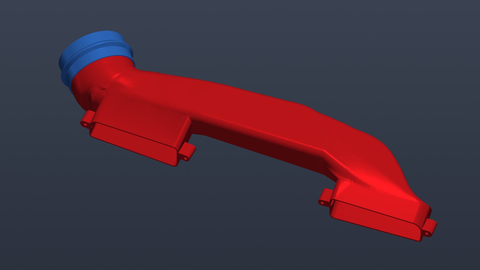
The new duct
Most of the loss in my intake is where the duct on the car today dumps its air into the airbox (the details are further down). So I redesigned the duct: the round end now matches the airbox socket, and the passage stays wide all the way across the car, from the driver snorkel to the round end.
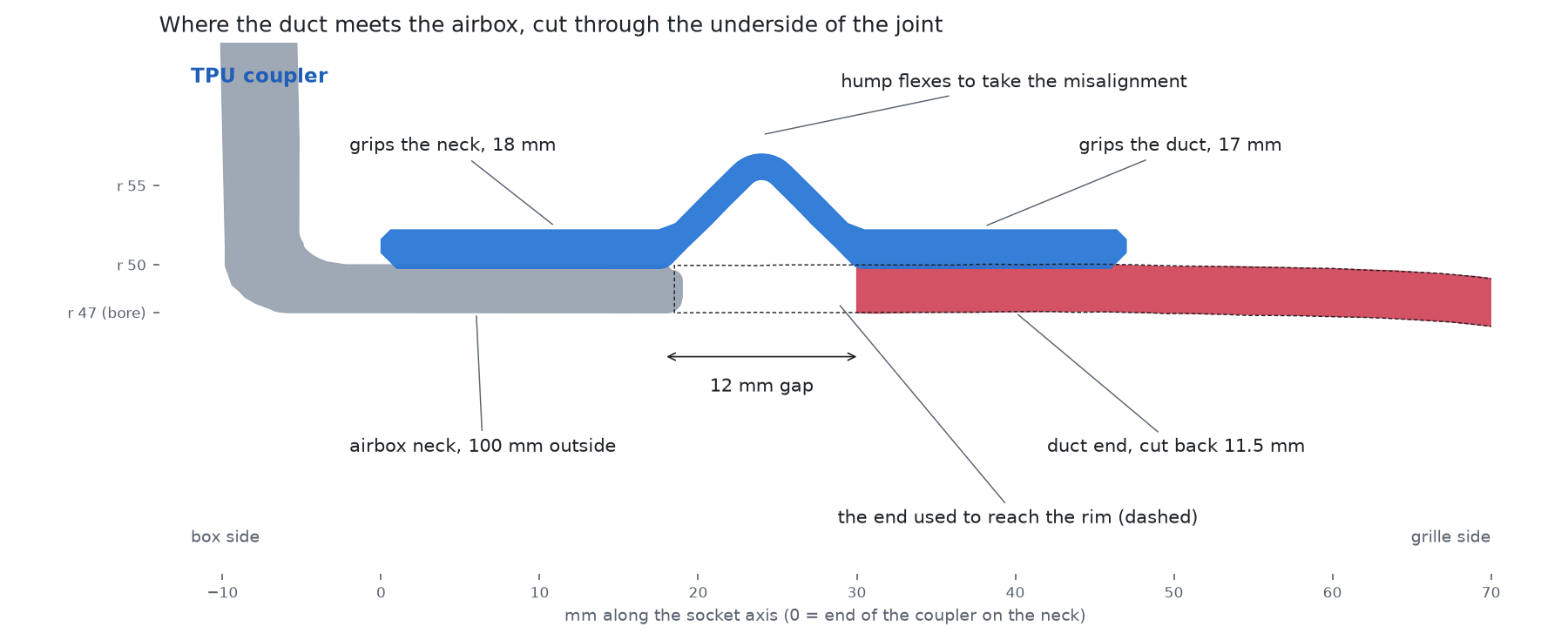
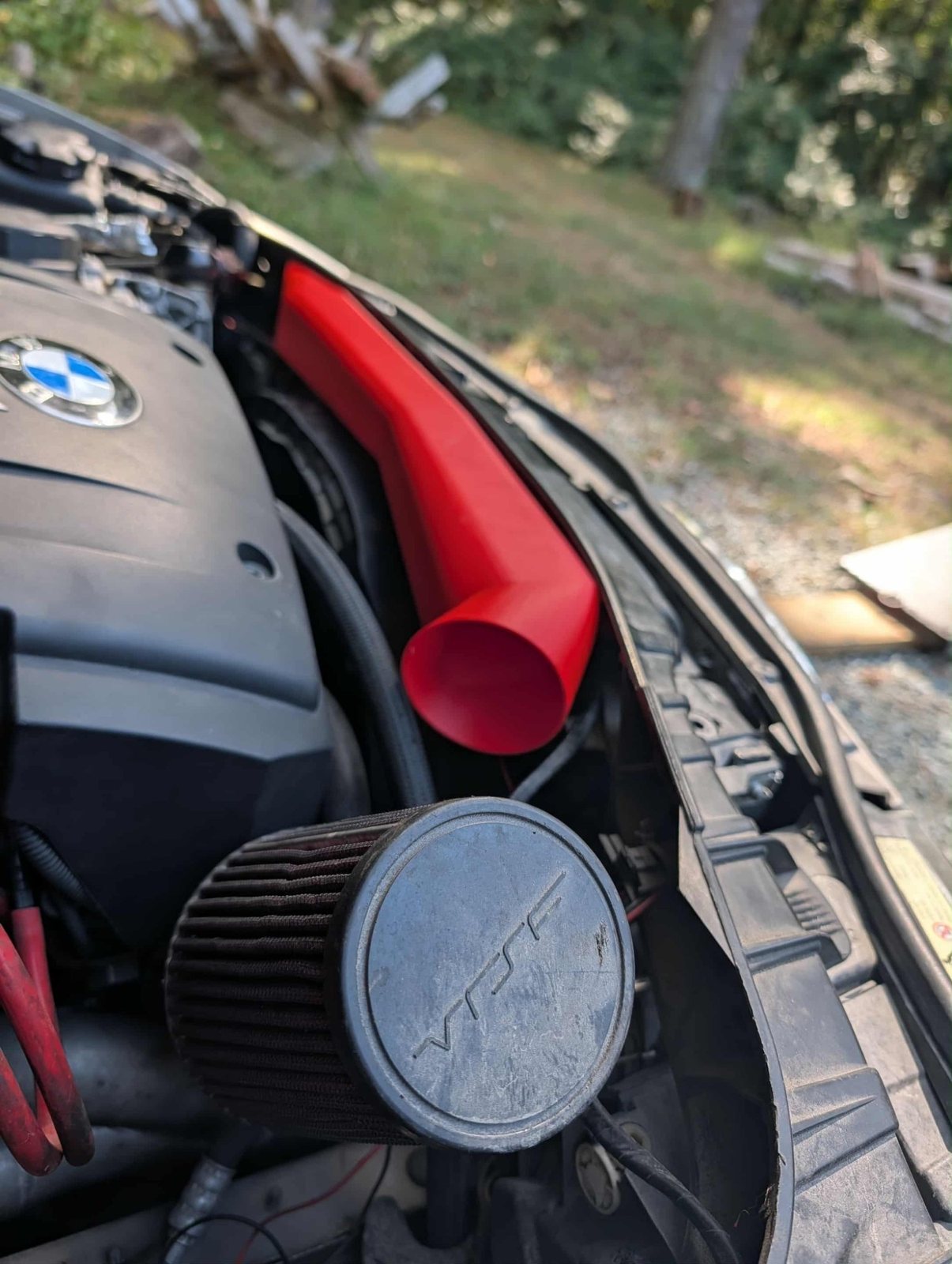
- The round end. 100 mm outside and 94 mm bore, the same as the airbox socket, so the bore runs straight on into the box. The duct and the box never line up perfectly on the car, which is why today's duct has a TPU ring where it goes into the socket. So the new end stops 12 mm short of the socket rim and a soft TPU coupler joins them: it grips the neck for 18 mm and the duct for 17 mm, with a flexible hump over the gap. The neck is only about 20 mm long on its underside, which is as far as the coupler can go onto it.
- The back of the duct. It sits about 20 mm further back from the middle of the car out to the passenger end, then turns into the round end in one smooth bend. Through the middle the passage is 34 to 46% bigger.
- The driver side. The back wall also moves rearward across the whole driver snorkel socket, up to 38 mm, and fades back into the old wall at the driver end, where there's no room behind it. The narrowest part, where the driver snorkel's air joins the crossing, goes from about 2,300 to 3,550 mm².
- What stays. The front wall and both snorkel sockets with their lugs are unchanged, so the snorkels bolt on as before.
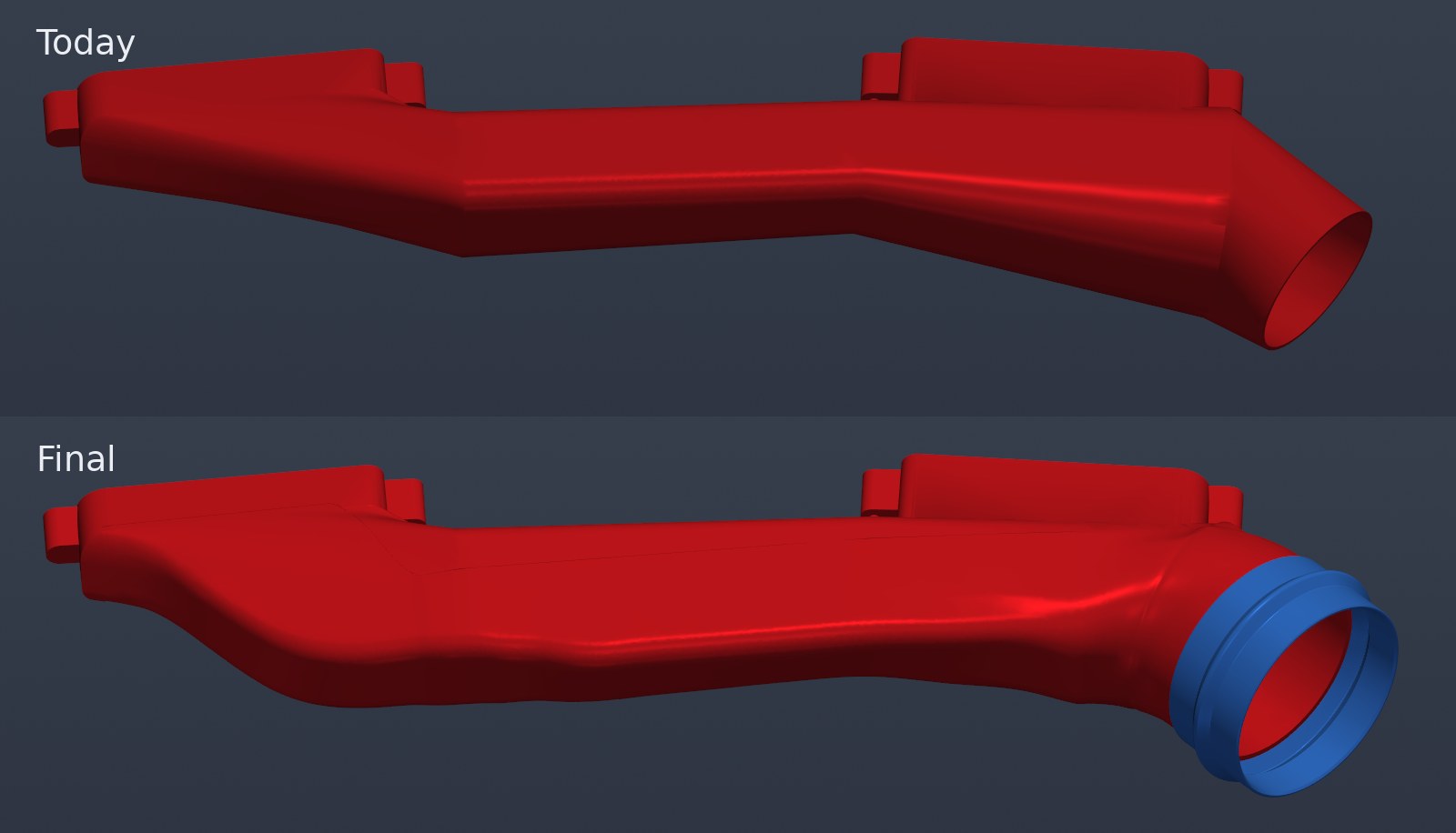
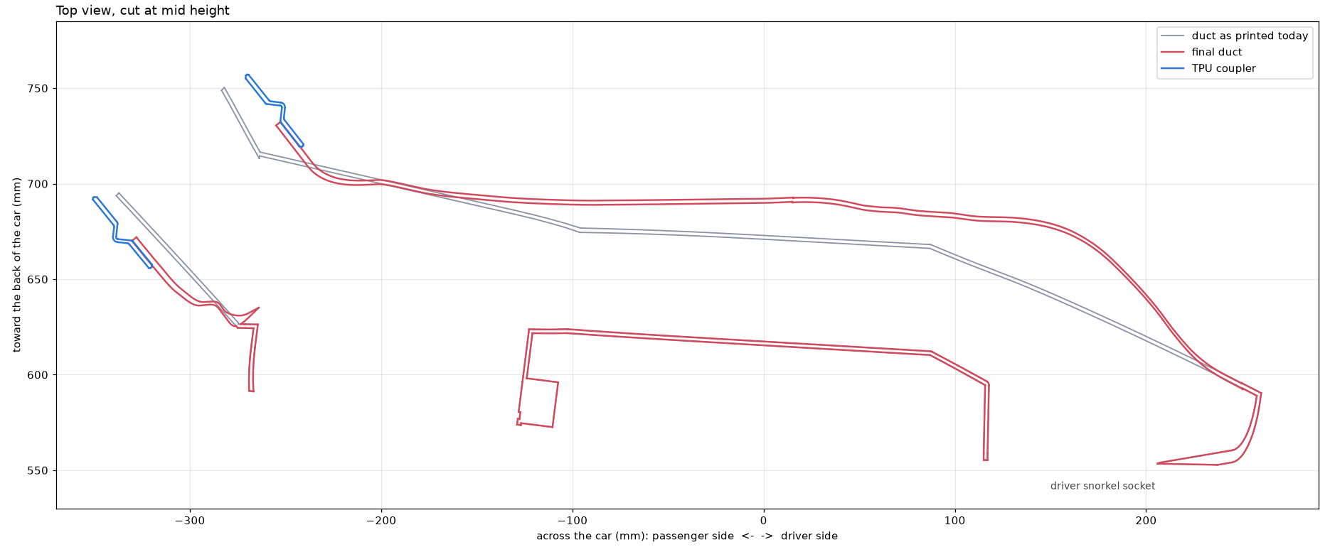
Same CFD for both, same 0.48 kg/s, same assumed filters, both on the coarse mesh (on today's duct the coarse mesh came within 0.5% of the finer one):
| Duct today | New duct | |
|---|---|---|
| Total pressure lost before the turbos | 12.8 kPa | 9.2 kPa |
| Vacuum in the turbo pipes | 18.7 kPa | 15.7 kPa |
| Air leaving the duct into the box | 93 m/s | 57 m/s |
| Share of the air through the driver snorkel | 29% | 33% |
That is 3.6 kPa less lost before the turbos, 28%, and 3 kPa less vacuum in the turbo pipes. Most of it is the round end: the air leaves the duct at 57 m/s instead of 93, so much less of its speed is thrown away in the box. The driver snorkel now carries a third of the air instead of 29%, so the passenger snorkel and its flange work less hard. In the turbo model further down that is worth about 4 whp at the same boost.
Where the pressure goes
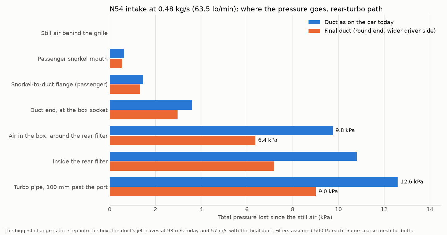
Both on the same coarse mesh, so they compare directly (on the duct today the finer mesh lands within 0.3% of it overall):
| Step, rear-turbo path | Duct today | New duct |
|---|---|---|
| Still air to the duct's end at the box (snorkel, flange, duct) | 3.6 kPa (29%) | 3.0 kPa (33%) |
| The duct's jet dumping into the box | 6.2 kPa (49%) | 3.4 kPa (38%) |
| Through the filter | 1.0 kPa (8%) | 0.8 kPa (9%) |
| Into the turbo pipe and down it | 1.8 kPa (14%) | 1.8 kPa (20%) |
| Total | 12.6 kPa | 9.0 kPa |
The new duct nearly halves the biggest step, the jet dumping into the box, from 6.2 to 3.4 kPa. Its round end fills the socket, so the air leaves at 57 m/s instead of 93, and the wider driver side feeds the jet more evenly. The duct itself loses a little less on the way, 3.0 kPa to its end against 3.6. The filter and the turbo pipe barely change, so they are now a bigger share of a smaller total.
On today's duct that jet is the big one. Its round end is about 74 mm across inside, sitting in a 94 mm socket, and all the air leaves it at about 93 m/s, up to about 170 m/s on the inside of its last bend. Nothing in the box slows that jet down gently, so its speed, 5 to 6.5 kPa worth, is simply lost. The front filter sits in the jet's path and soaks up a lot of it: 3 to 4 kPa goes in its media against about 1 kPa in the rear filter. Either way it's gone before the turbos.
I haven't printed the new duct yet, so the files on Cults3D are still the duct as it is on the car today.
Print it yourself
All three are STLs on Cults3D. The airbox needs the duct, and the duct takes its air from the snorkels.
The lid and the hood
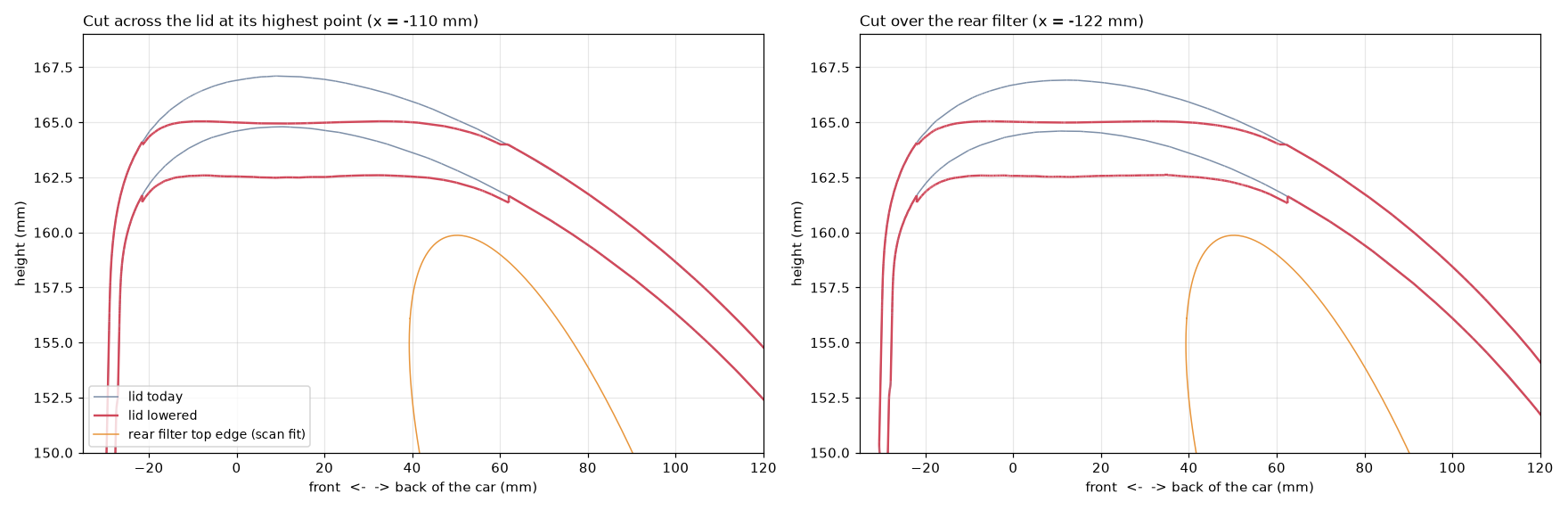
The top of the lid touched the hood. Its highest point is the dome over the rear filter, so I lowered that by 2 mm: the lid above 164 mm is the same shell pressed down, by nothing at 164 mm and by 2 mm at the old peak, so the dome just gets flatter. The wall stays 2.4 mm, the front lid screw boss comes down with it, and the rear filter's top edge still clears the underside by about 2 mm. The front filter sits under a lower part of the lid and doesn't change.
With the lid off
Taking the lid off is the baseline: nothing between the filters and the engine bay. I modelled the opening the lid covers as still air at ambient pressure, with the snorkels and duct still connected, so the air can come from either.
| Lid on, duct today | Lid on, new duct | Lid off | |
|---|---|---|---|
| Total pressure lost before the turbos | 12.8 kPa | 9.2 kPa | 2.4 kPa |
| Vacuum in the turbo pipes | 18.7 kPa | 15.7 kPa | 8.6 kPa |
| Air coming through the snorkels and duct | 100% | 100% | 5% |
With the lid off, 95% of the air comes straight in over the box. What's left is the filters and the entry into the turbo pipes. So the sealed box costs about 10 kPa with today's duct and 7 with the new one. On the car the hood sits on the lid, so with it off the air would have to come in through a 10 to 15 mm gap under the hood. This is the best case for an open box.
Hot air
The catch with an open lid is that the filters breathe engine-bay air, and the bay is hot. The sealed box isn't free of heat either: it sits above the turbo and heat soaks.
For the box I carried the temperature through the solved airflow with the box, lid and filter caps held hot. At full throttle the air picks up about 9% of the difference between the box and the incoming air with today's duct, 7% with the new one: a box soaked 90 °F hotter than the air warms it about 7 to 8 °F before the turbos. That is a high estimate. At part throttle the air sits in the box longer and comes out hotter, but a full-throttle pull replaces it in a few hundredths of a second.
To turn temperatures and pressure losses into power I used a simple turbo model: the tune holds 23 psi, the compressors run at 70%, the intercooler at 75% against 77 °F air, the meth takes 27 °F off the charge, and power at a held boost follows the air density in the manifold. 550 whp is the car as it is now. Those are assumptions, not measurements, and the answers are differences between setups, not dyno numbers.
| On a 77 °F day | Air into the turbos | Charge air (logged IAT) | Estimate |
|---|---|---|---|
| Sealed box, duct today, box heat soaked | 84 °F | 125 °F | 550 whp |
| Sealed box, new duct | 83 °F | 121 °F | 554 whp |
| Lid off, filters in 113 °F air | 113 °F | 127 °F | 550 whp |
| Lid off, filters in 140 °F air | 137 °F | 136 °F | 541 whp |
| Lid off, filters in 167 °F air | 162 °F | 145 °F | 531 whp |
The open lid only matches the sealed box if the air the filters breathe is less than about 36 °F above ambient, 24 °F against the new duct. Near the turbos it is usually hotter than that, so the sealed box wins, by about 9 whp against 140 °F bay air and 19 whp against 167 °F. The intercooler is why the gap isn't bigger: at 75% it takes out about three quarters of any change in inlet temperature before the manifold, where the N54 reads IAT. With a weaker intercooler the gap grows to 14 and 27 whp. The model leaves out timing pulled for a hotter IAT, which would make an open lid look worse still.
On track my engine bay runs well over 120 °F, and on a hot day it climbs about the same amount above the outside air. So what matters is how far the bay sits above ambient. Same model, with the sealed box heat soaked and the turbo pipes at bay temperature:
| Bay above ambient | Bay on a 77 / 90 °F day | Lid off against today's box | Lid off against the new duct |
|---|---|---|---|
| 43 °F | 120 / 133 °F | -2 whp | -6 to -7 whp |
| 55 °F | 132 / 145 °F | -5 to -7 whp | -10 to -11 whp |
| 65 °F | 142 / 155 °F | -9 to -10 whp | -13 to -15 whp |
| 75 °F | 152 / 165 °F | -12 to -13 whp | -16 to -18 whp |
The margin hardly changes with the day. A hot day costs every setup about the same, around 14 whp at 90 °F and 25 at 100 °F, through the intercooler. The open lid only breaks even when the bay is less than about 36 °F above ambient, 24 °F against the new duct, so with my bay well over 120 °F the sealed box stays ahead, and the hotter the bay runs the more it wins.
Wastegate duty
The tune holds boost, so the box's restriction comes back as work the turbos have to do. At the same air temperature the sealed box with today's duct needs a pressure ratio of 3.05 against 2.73 with the lid off: 13% more compressor work, 8% with the new duct. The wastegates find it by sending more exhaust through the turbines, which shows up as a higher wastegate duty cycle at the same rpm and boost. That extra work heats the air again, about 34 °F at the compressor outlet and 9 °F after the intercooler.
The cold air in the box more than pays it back. Against an open lid in 140 °F bay air, the sealed box needs only 3% more compressor work with today's duct and 1.5% less with the new one, and its charge comes out 11 °F cooler. I can't put a duty cycle percentage on it without the tune's wastegate tables; a log at the same rpm and boost with the lid on and off will show it. On the 17Ts near the top of their range the restriction also pushes the compressors about 7% further toward their flow limit, 2.5% with the new duct. If they run out of room, that shows up as boost falling off at high rpm instead.
The parts on the car today
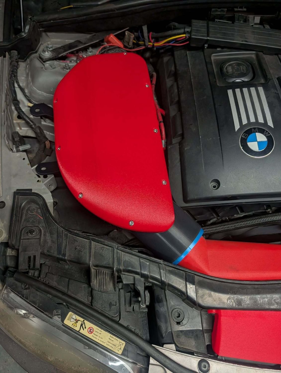
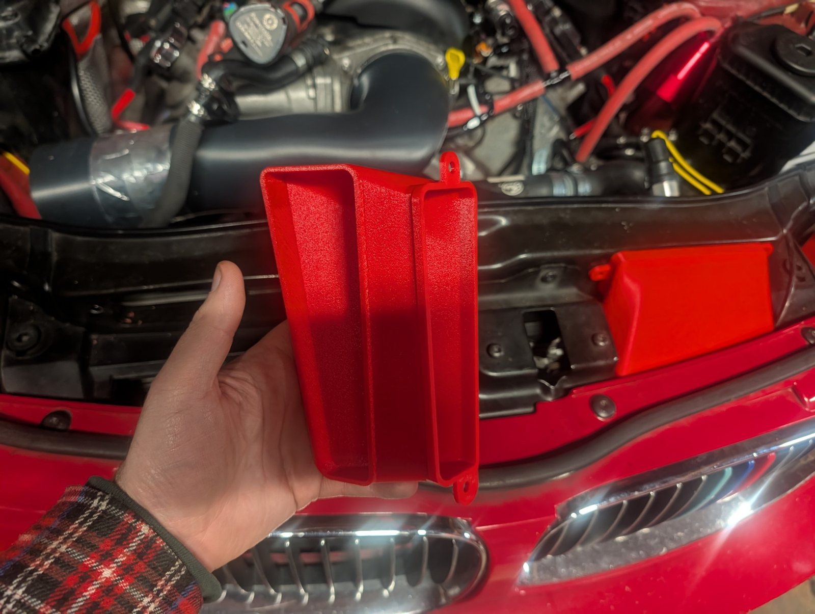
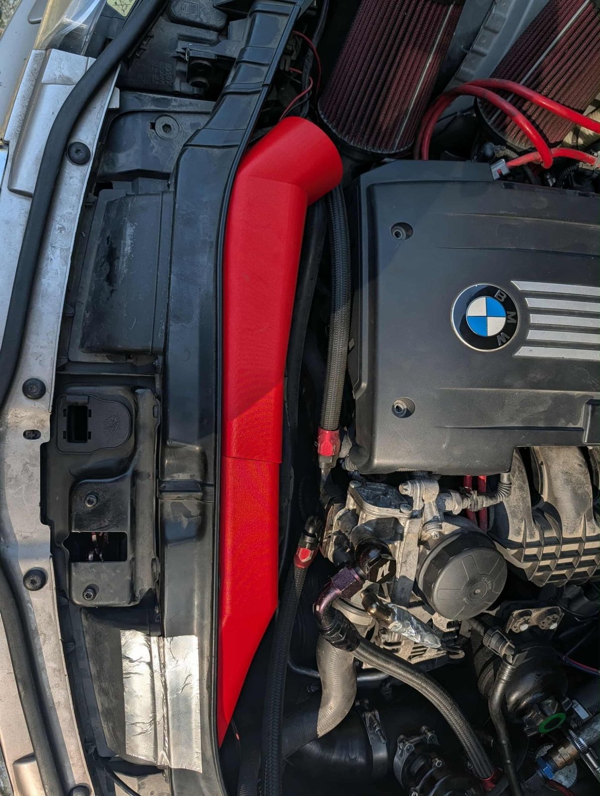
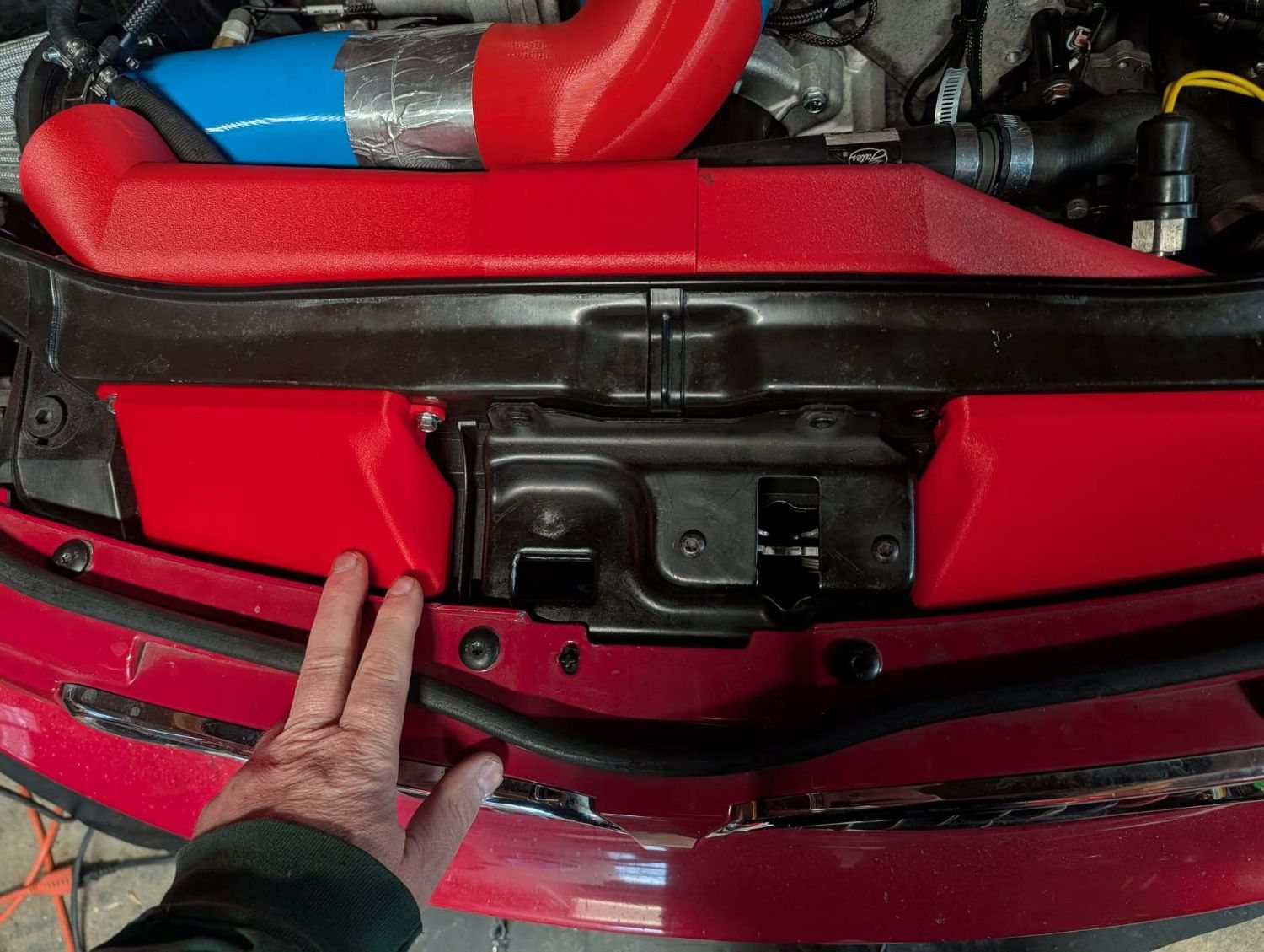
Three printed pieces take the air from behind the grille to the turbo inlet pipes. Each is an STL on Cults3D.
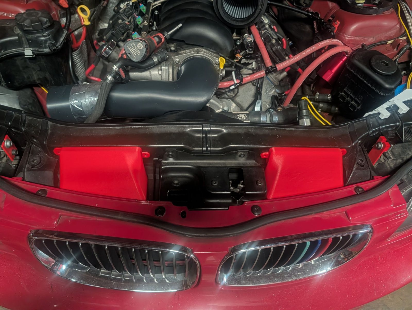
- Grille snorkels. Two boxes that bolt behind the kidney grille openings and pick the air up right there, ahead of the radiator. My red LS-swapped 135i runs the same pair into its own intake. Listed as the E82 air intake duct.
- Relocated inlet duct. Runs across the radiator support from the snorkels to the airbox. The E82 135i relocated inlet air duct.
- Sealed airbox. A box and a screw-down lid around the two cone filters on the turbo inlet pipes, so the turbos only see the ducted air. TPU gaskets seal the duct into its socket and the floor ports around the pipes. The E82 N54 relocated inlet airbox.
What the CFD says about today's duct
At 0.48 kg/s, half to each turbo, starting from still air behind the grille, with each filter assumed to drop 500 Pa:
| Front turbo pipe | Rear turbo pipe | |
|---|---|---|
| Total pressure lost | 12.96 kPa | 12.52 kPa |
| Vacuum in the pipe | 18.6 kPa | 18.9 kPa |
About 12.7 kPa (1.85 psi) of total pressure is gone before the turbos. The vacuum in the pipes is bigger, about 18.8 kPa, because it also includes the speed of the air itself: 82 m/s in a 55.6 mm pipe is about 4 kPa that isn't lost, just moving. The compressors start from about 89 kPa absolute instead of 101, so for the same boost each turbo works at a pressure ratio about 14% higher.
The two snorkels don't share the work. The passenger one, next to where the duct turns into the box, takes 71% of the air. The driver one's air has to cross the car through the duct's narrowest stretch, about 2,300 mm² at close to 50 m/s, so it takes 29%.
How I got to the new duct
In two steps, each through the same CFD on the coarse mesh. The first was just the round end and the wide back:
| Duct today | First step | |
|---|---|---|
| Total pressure lost before the turbos | 12.8 kPa | 9.7 kPa |
| Vacuum in the turbo pipes | 18.7 kPa | 16.1 kPa |
| Air leaving the duct into the box | 93 m/s | 57 m/s |
| Share of the air through the driver snorkel | 29% | 30% |
That alone took off 3.1 kPa, about a quarter, almost all of it from the round end.
Along the way I tried a wider middle that narrowed back to the old duct before the passenger snorkel. It came out worse than the round end on its own, 9.9 kPa against 9.4: the air slows down in the wide part and then has to speed up again. Keeping it wide all the way to the end is what made the difference.
Then the driver side
The driver snorkel's air still had to squeeze through the narrowest part of the duct, where the driver socket feeds into the crossing: about 2,440 mm² at 48 m/s. So I widened the driver side too, starting right at the socket behind the grille. The back wall moves rearward from the middle of the car across the whole driver socket, up to 38 mm, and fades back into the old wall at the driver end, where there's no room behind it. The front wall, the socket and its lugs are the same, so the driver snorkel bolts on as before.
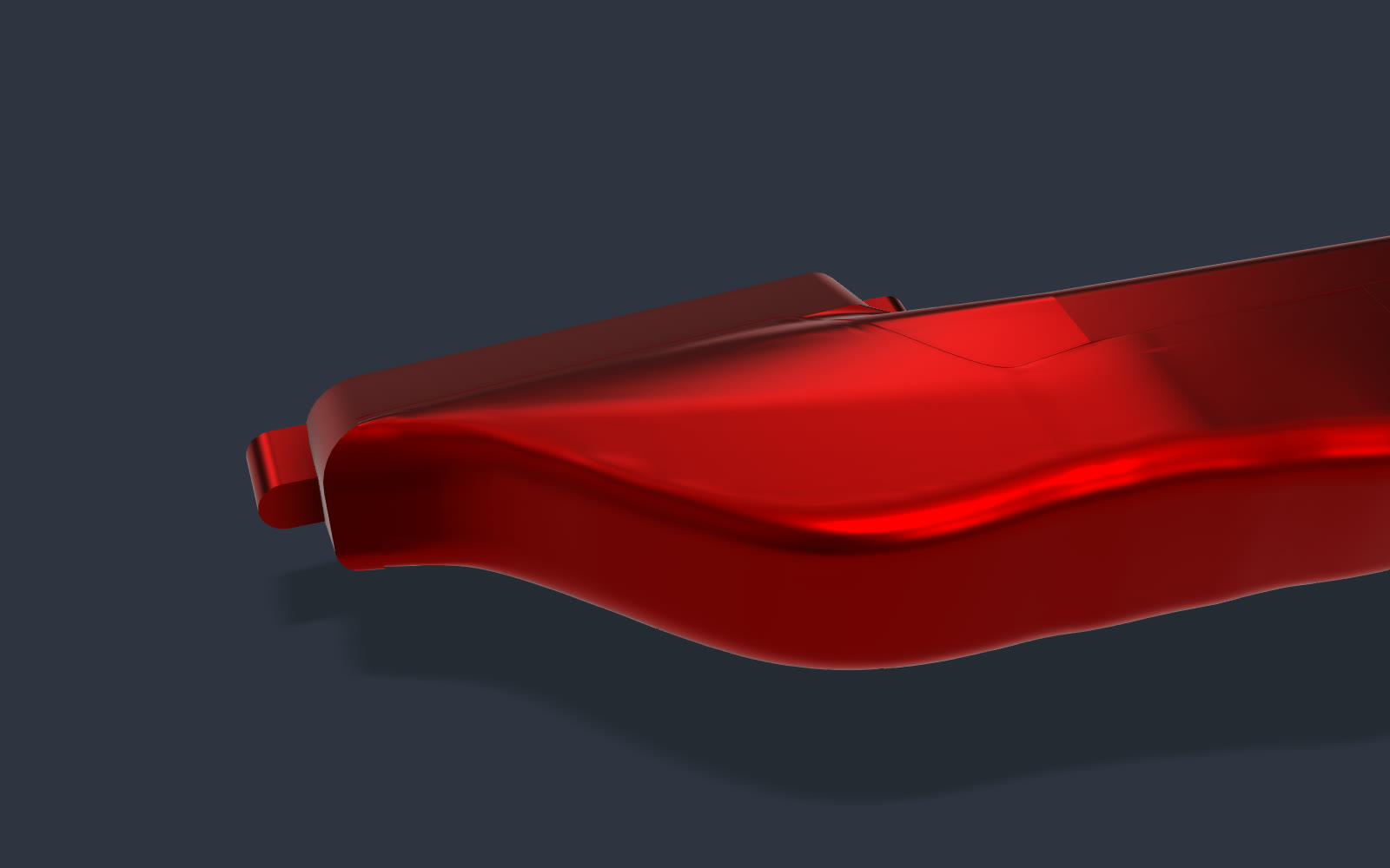
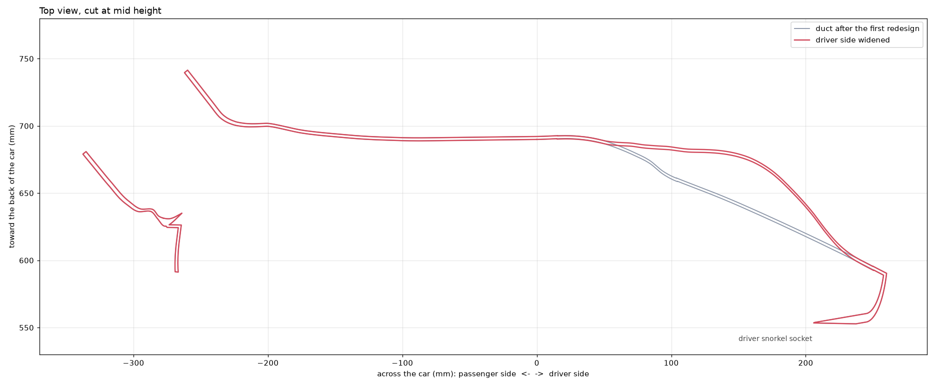
The narrowest part goes from about 2,440 to 3,550 mm², the same as the crossing, and the chamber behind the driver snorkel is 36 to 53% bigger. Same CFD again:
| First step | Wider driver side | |
|---|---|---|
| Total pressure lost before the turbos | 9.7 kPa | 9.2 kPa |
| Vacuum in the turbo pipes | 16.1 kPa | 15.7 kPa |
| Share of the air through the driver snorkel | 30% | 33% |
| Driver air in the narrowest part | 48 m/s | 38 m/s |
That is another 0.5 kPa off, to 9.2 kPa. The driver snorkel now carries a third of the air instead of 30%, and the jet into the box is fed more evenly.
How it was modelled
- The parts. The snorkels, duct, airbox and lid come straight from their Fusion 360 models, placed as they sit on the car.
- The engine bay. The cone filters and turbo inlet pipes come from 3D scans of the bay with and without the filters. Each filter is about 157 mm long, 114 mm across the base and 81 mm across the top. The pipes are 60.6 mm outside; I assumed a 2.5 mm wall.
- Gaskets. Assumed to seal perfectly: the duct in its socket, the pipes in the floor ports, the lid seam and each snorkel's flange.
- Airflow. 0.48 kg/s (63.5 lb/min), what an N54 needs for about 550 whp: about 10 crank hp per lb/min and 15% through the drivetrain. That is a target, not a dyno sheet.
- Filters. Each a 12 mm porous layer on the scanned cone, set to 500 Pa at its share of the flow. That figure is assumed, not measured.
- The solve. Steady flow in OpenFOAM, k-omega SST, about 864,000 cells, starting from still air under each snorkel. The answer moved under 1% over the last 1,000 iterations, a coarser mesh of 503,000 cells landed within 0.5% of it, and the air in and out adds up at every step from the snorkels to the box.
What this does not show
- No road speed. The air under the snorkels is still. At 100 mph the grille sees up to about 1.2 kPa of ram pressure, which would offset part of the loss.
- Airflow and filters are estimates. Losses go with the square of the flow: 10% more air is about 21% more loss.
- Incompressible model. At 93 m/s the air's density changes a few percent, and more on the inside of the duct's last bend at about 170 m/s, so treat these as estimates. That bend is probably a little worse than shown.
- Not horsepower. These are pressures in a simulated intake, not a measurement on the car. The pressure CAN node is a board I've designed to measure them; it isn't built yet. Its two 40 kPa channels cover the 19 kPa in the turbo pipes, and the 10 kPa ones suit the steps before the box.