Cold air intake: the whole tract in CFD
A printed front snorkel and round airbox for my F56, modelled as one piece of air from the two grille ports to the factory MAF neck before anything gets printed. Then changed where the flow said it was losing, and run again.
What it is
Three printed parts replace the factory snorkel and airbox. I used scans of my engine bay to lay out the parts. The new housing clears the design height limit by 5.4 mm. Its left side and floor still need a fit check on the car.
- Snorkel. Two ports that sit in the radiator shroud's openings, lofted into one trunk. The ports are 131 × 34.5 mm, as big as the shroud allows, and the roof runs up to 3 mm over the factory lid line.
- Flange joint. The snorkel bolts to the airbox with six M4 screws into heat-set inserts, with a thin lip across the top where there is no room for a flange.
- Airbox. A 187 mm drum with a domed end cap, an inverted-cone dry filter, a 74 mm radius elbow and a copy of the factory neck, so the factory MAF bolts on and the factory coupler clamps on.
- Mounts. Printed bosses drop over the two M8 studs at the front of the car. At the back, a bolt-on bracket puts two pins into the factory airbox mounts, with new TPU sleeves where the rubber had melted away.
The earlier assembly
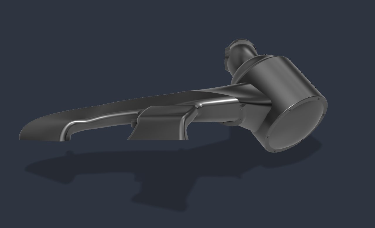
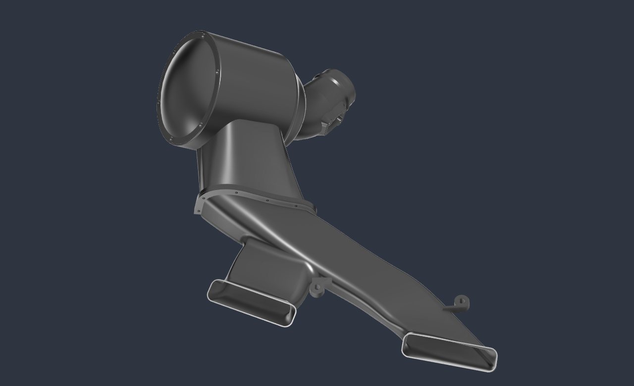
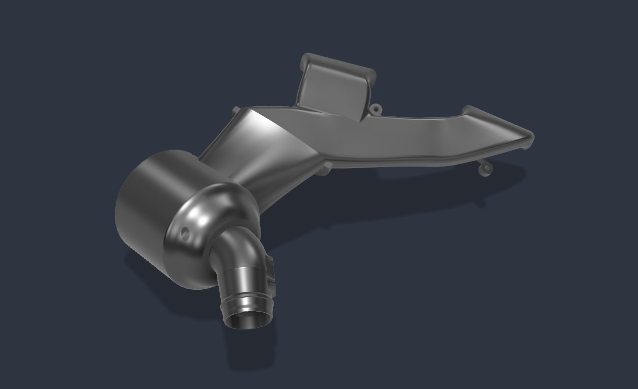
The wider spout
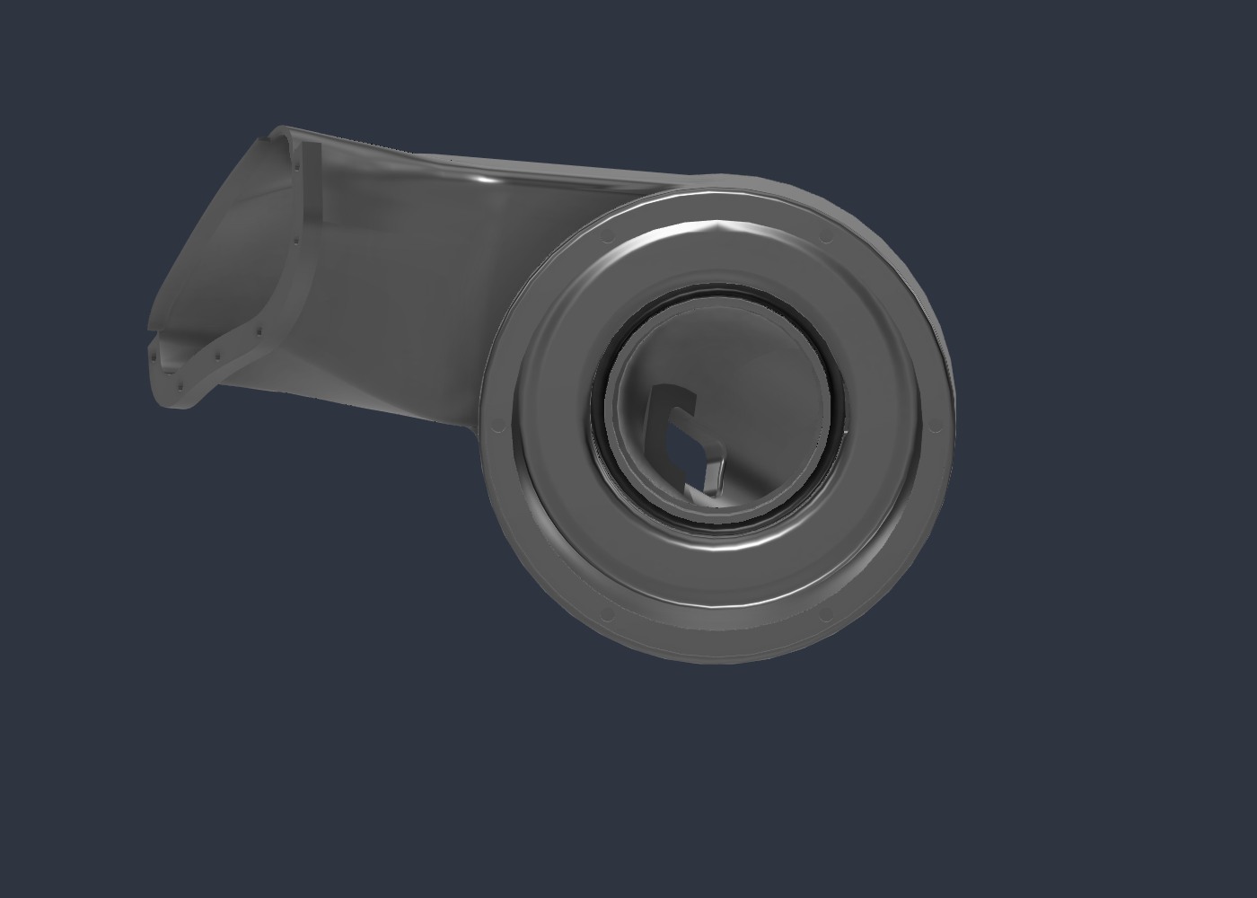
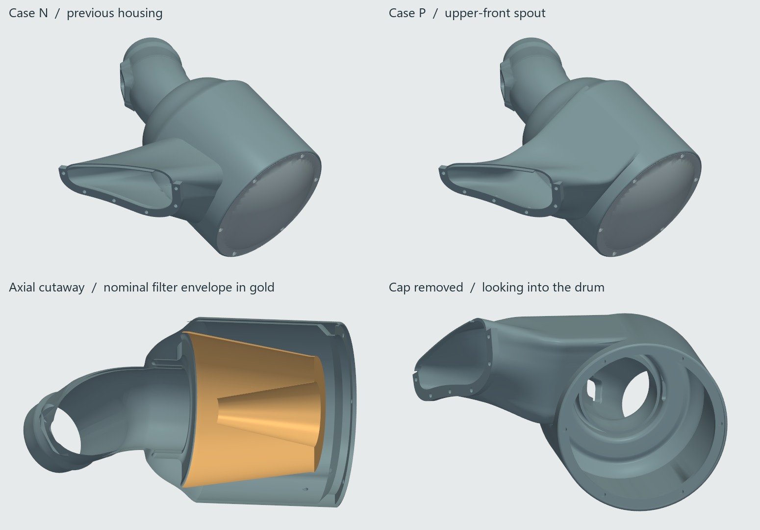
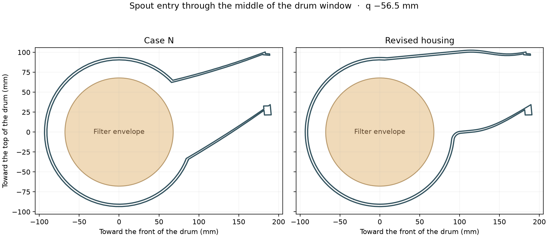
I kept the six-bolt joint and opened up the other end of the spout around the upper front of the drum. The opening measures 156 cm² along the curved wall. The outside rolls into the drum over a 15 mm radius. Inside, the floor turns into the drum over a radius of up to 12 mm.
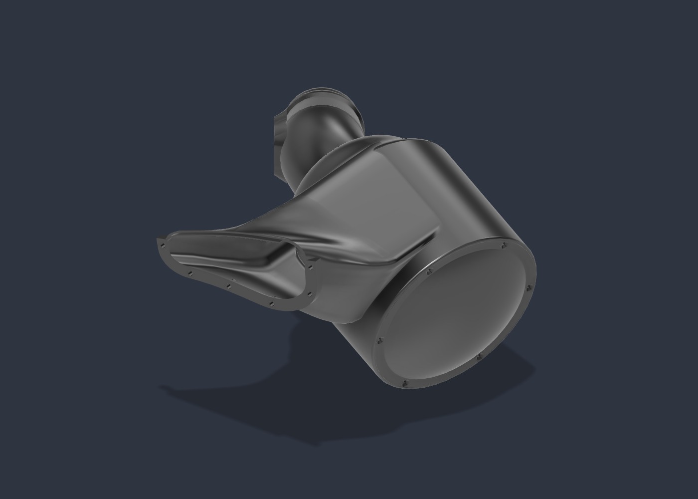
The filter
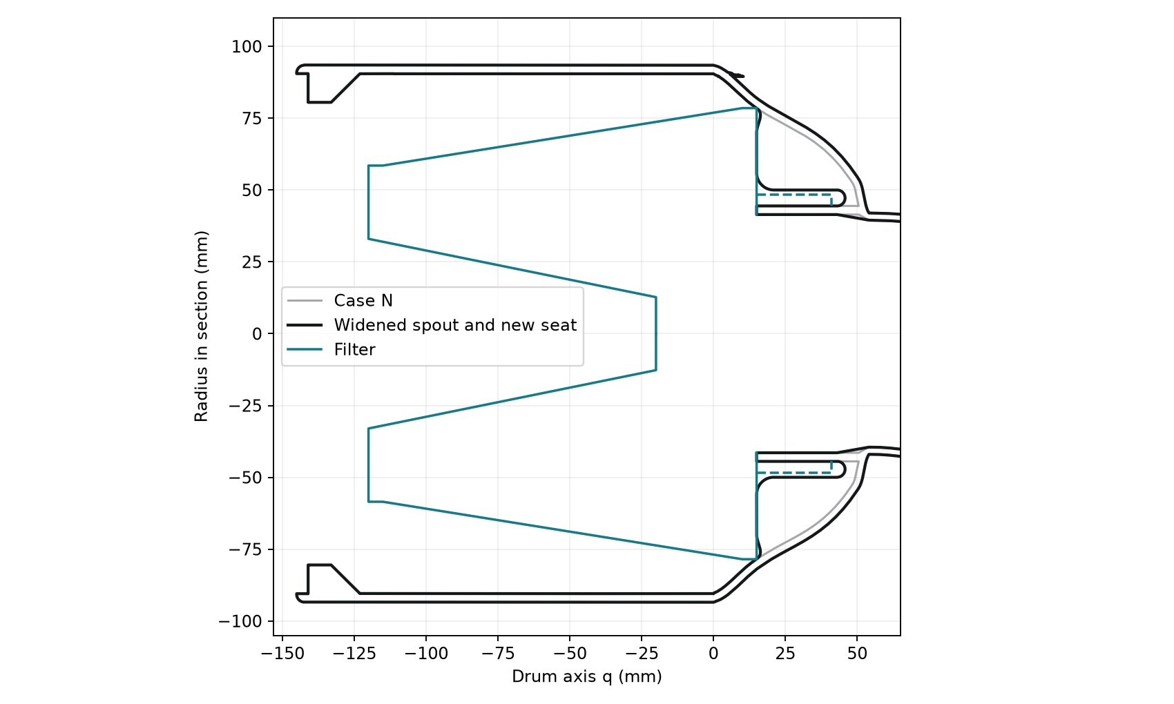
The housing is built around a KYOSTAR KD2045, a universal dry cone with an inverted top (the one I ordered; KD2045RD is the red one). Every size below is designed into the drum, the spigot and the cap.
| Part | KYOSTAR KD2045 |
|---|---|
| Flange | 3.5 in (89 mm) ID, 26 mm long collar on a 28 mm housing spigot |
| Base | 157 mm OD |
| Top | 117 mm OD |
| Element height | 130 mm |
| Top shape | Inverted: a 66 mm opening in the top ring with a pleated cone inside it, ending in a 1 in plug |
| Media | Dry, washable |
| Flow rating | None published |
How it was modelled
- One model, ports to coupler. Both ports open to still air at ambient pressure, so the split between them is worked out, not assumed. The engine's pull is a fixed flow at the end of the MAF neck.
- Real flow numbers. 355 CFM is the most my car has pulled in any logged pull (694 kg/h at 6,000 rpm). 563 CFM is my estimate for 350 whp.
- Mesh and solver. OpenFOAM, steady, k-omega SST, about 2.2 million cells with 1 mm cells on every wall. The geometry comes straight out of the CAD.
- The filter. A porous layer in the shape of the cone and its inverted front. The filter maker publishes no flow rating, so its resistance is an assumption, the same in every run. Treat the filter's share of the loss as the soft number here.
The flow
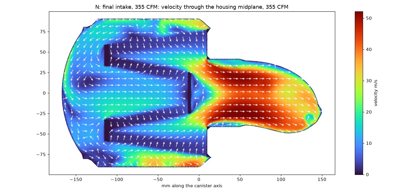
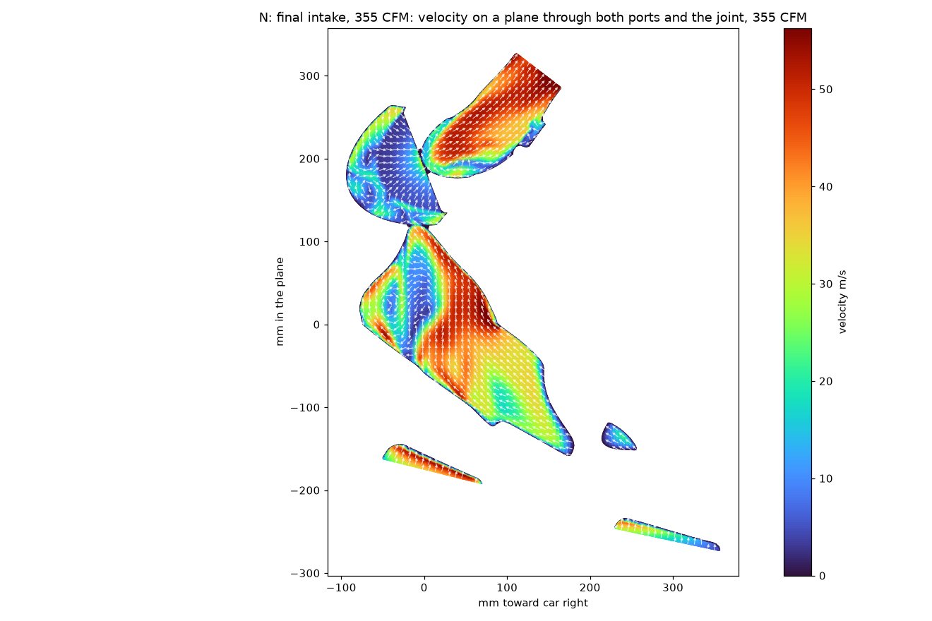
Arrows ride the air from both ports, through the trunk and the joint, round the drum, through the filter and out the neck, coloured by speed. They are slowed down so you can follow them.
355 CFM at my logged peak
563 CFM at the estimated 350 whp flow
Watch the earlier designs at 355 CFM
What the wider spout changed
"Coupler vacuum" is what a gauge on the factory coupler would read: everything the intake costs plus the speed of the air in the factory neck, which the stock box pays too.
| Measurement | First design | Earlier spout | Wider spout |
|---|---|---|---|
| Total loss, 355 CFM | 3,274 Pa | 2,759 Pa | 2,657 Pa |
| Coupler vacuum, 355 CFM | 4,416 Pa (0.64 psi) | 3,901 Pa (0.57 psi) | 3,798 Pa (0.55 psi) |
| Total loss, 563 CFM | 7,734 Pa | 5,888 Pa | 5,844 Pa |
| Coupler vacuum, 563 CFM | 10,604 Pa (1.54 psi) | 8,758 Pa (1.27 psi) | 8,714 Pa (1.26 psi) |
| Port 1 / port 2 | 65 / 35 % | 66 / 34 % | 66 / 34 % |
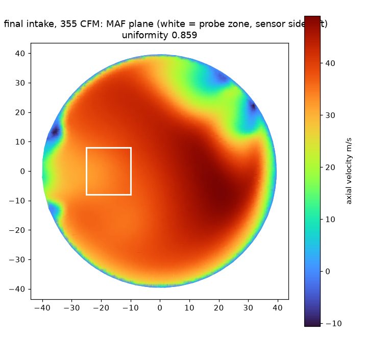
| MAF uniformity, 355 CFM | 0.831 | 0.859 | 0.841 |
At my logged peak the whole intake costs 103 Pa less, but the loss from the joint into the drum rises from 311 to 384 Pa. The fast stream follows the right wall. At 65 mm behind the joint, air is moving backward across 20.4% of the wider passage. The earlier spout measured 9.6% at the same spot.
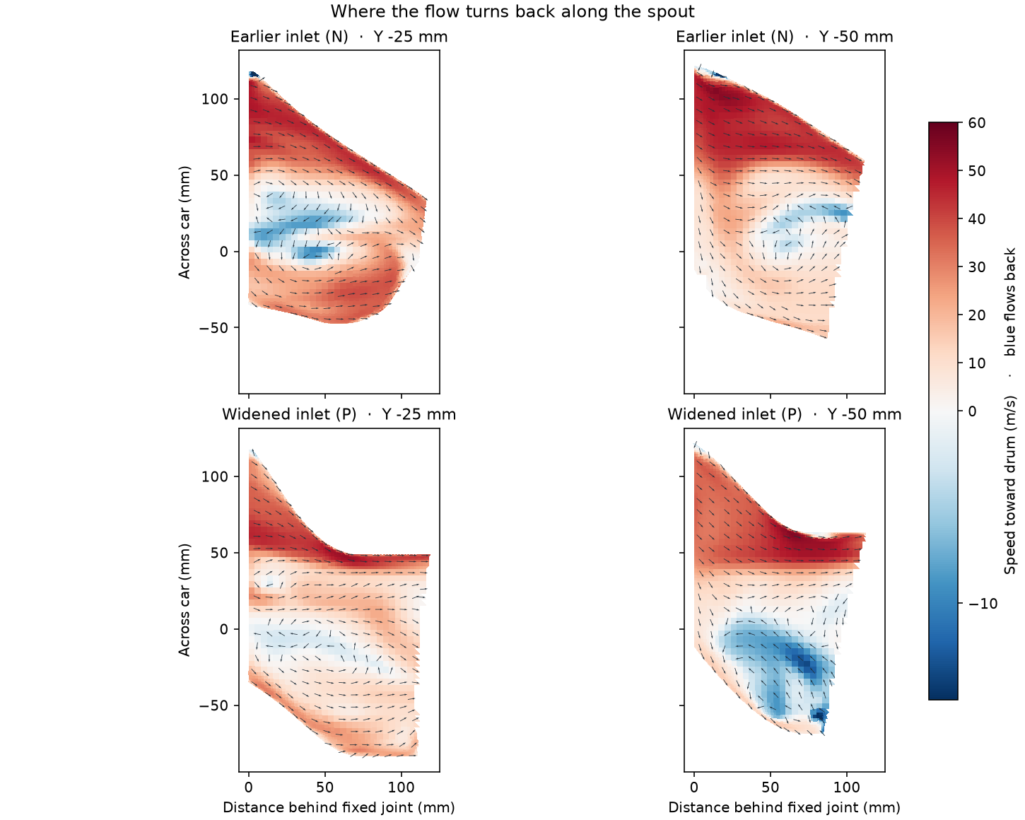
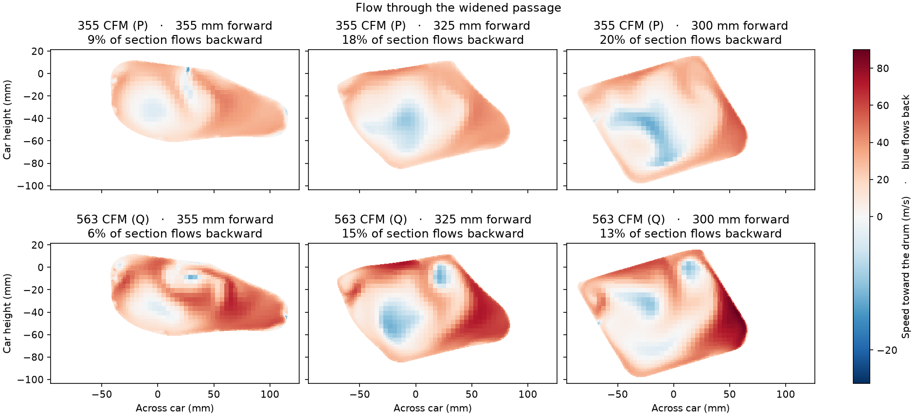
At 355 CFM the MAF probe sits in air moving 23% faster than the bore average, up from 6% with the earlier spout. At 563 CFM the wider intake saves 44 Pa in the final field and 85 Pa averaged over the last 300 iterations. Both high-flow runs fluctuate by more than that difference.
Where the loss went at 355 CFM
| Stretch (355 CFM) | First design | Earlier spout | Wider spout | Changes in the earlier design |
|---|---|---|---|---|
| Ports to the joint | 868 Pa | 795 Pa | 589 Pa | Bigger ports, roof up 1 mm |
| Spout into the drum | 469 Pa | 311 Pa | 384 Pa | Spout lofted straight onto the snorkel's outlet |
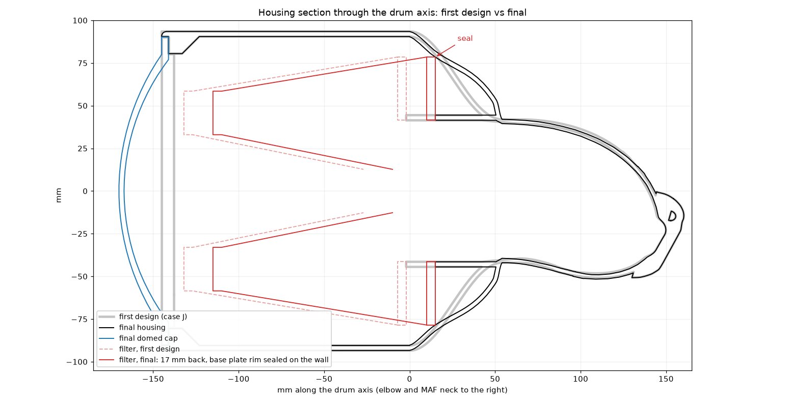
| Into the inverted cone | 550 Pa | 255 Pa | 351 Pa | Domed cap and filter 17 mm further back: 38 to 52 mm in front of it instead of 9 |
| Filter media | 390 Pa | 471 Pa | 362 Pa | Base sealed on the housing wall, so the media right at the base sees less air |
| Filter to coupler | 997 Pa | 927 Pa | 971 Pa | Elbow radius 50 to 74 mm |
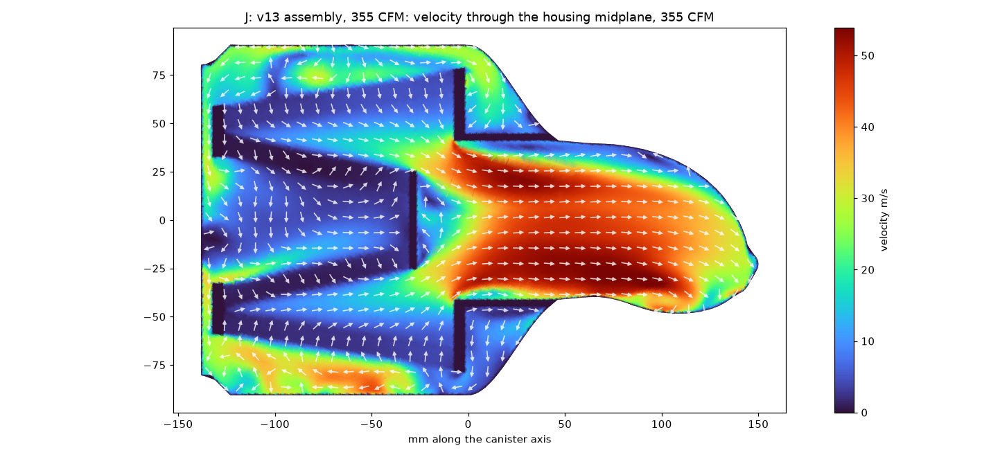
The stretch estimates use the average total pressure at the joint and samples from a plane through the drum. The filter resistance is assumed. The whole-intake comparison uses pressure at the coupler and the imposed airflow.
Mounting it
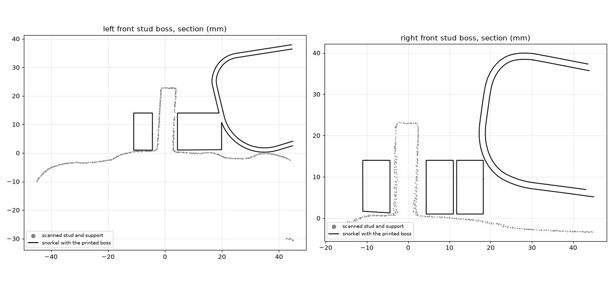
- Front. Two M8 studs come up out of the radiator support, square to it. Each gets a printed boss with an 8.8 mm hole, 13 mm tall, which leaves room on the stud for a washer and nut and a 13 mm socket.
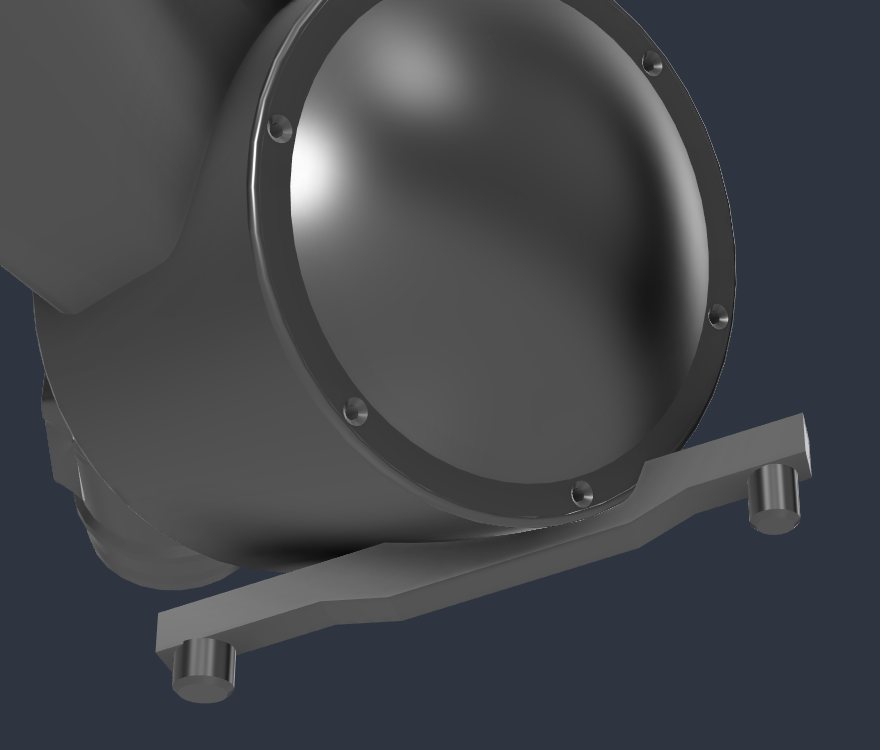
- Back. A bolt-on rail cradles the drum and holds it up from below, with two M5 screws down through the drum floor into heat-set inserts. Its two 12 mm pins drop into the two mounts the factory airbox used. Those were rubber and had melted to nothing on my car, so they get printed TPU sleeves.
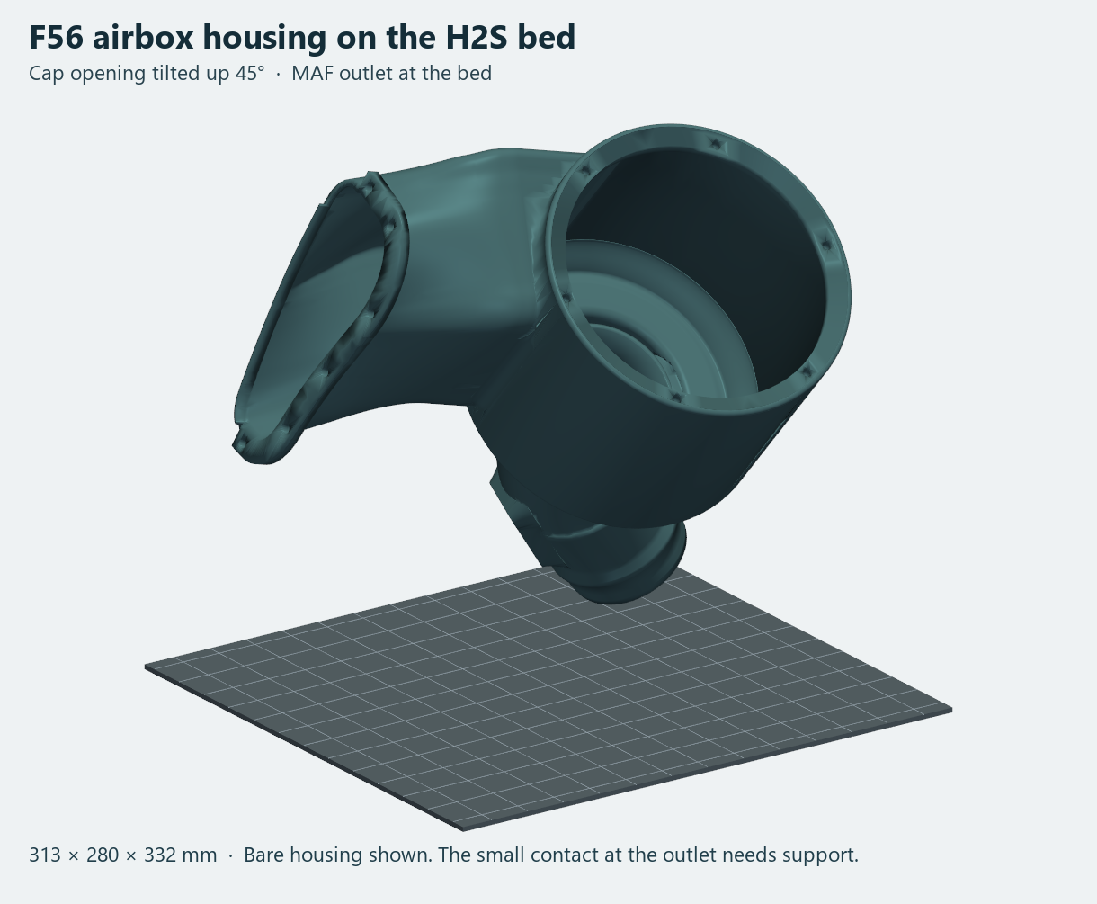
How the housing sits on the H2S
Next
The lower-left pocket is where I would test a guide vane. The widened housing also needs a test fit along the left wall and floor. The car has no sensor ahead of the turbo, so the coupler vacuum stays a CFD number until I put a gauge on the coupler.
The pressure CAN node is a board I've designed for measurements like this. It isn't built yet. Two of its six sensors read to 40 kPa for intake vacuum, so one ahead of the filter and one on the coupler would cover the 3.8 kPa this model predicts at 355 CFM and the 8.7 kPa at 563, and their difference is what the filter costs.